Information holder & nozzle se
Rating:
Components :
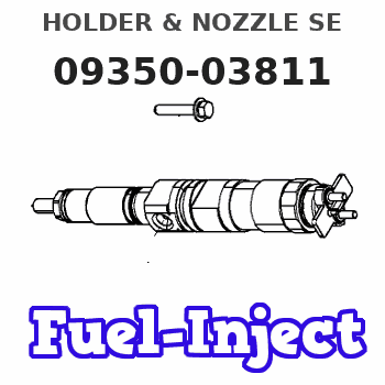
| 001. | HOLDER & NOZZLE SE | 09350-03811 |
Scheme ###:

| 000. | [01] | 09350-03811 | HOLDER & NOZZLE SE | 42634-13800 |
| 001. | [01] | 09310-03811 | HOLDER ASSY, NOZZL | |
| 001-001. | [01] | 09311-03811 | BODY SUB-ASSY, NOZ | |
| 001-002. | [01] | 09312-10330 | PIN, NOZZLE HOLDER | |
| 001-003. | [01] | 09312-70270 | SPRING, NOZZLE HOL | |
| 001-004. | [01] | 09313-10200 | SCREW, ADJUST | |
| 001-005. | [01] | 09313-40290 | NUT, CAP | |
| 001-005. | [01] | 09313-40150 | NUT, CAP | 09313-40150 |
| 001-006. | [01] | 09315-10380 | CONNECTOR, NOZZLE | |
| 001-007. | [01] | 09315-80010 | GASKET, INLET CONN | EZ0087405 |
| 001-008. | [01] | 09316-40781 | NUT, NOZZLE RETAIN | |
| 001-009. | [01] | 94918-00630 | SCREW, HOLLOW | |
| 001-009. | [01] | 94918-00152 | SCREW, HOLLOW | 00918-00152 |
| 001-010. | [01] | 09324-50052 | WASHER | ME022312 |
| 001-011. | [02] | 09022-20080 | WASHER, FUEL PIPE | MM500114 |
| 001-011. | [02] | 94901-81020 | WASHER, COPPER PLA | 94901-81020 |
| 002. | [01] | 09340-01910 | NOZZLE ASSY | 42634-01100 |
| 002. | [01] | 09340-02690 | NOZZLE ASSY | 42634-13810 |
Include in #3:
09350-03811
as HOLDER & NOZZLE SE
Cross reference number
| Part num | Firm num | Firm | Name |
| 09350-03811 | 42634-1380 | HOLDER & NOZZLE SE |
Information:
Start By:a. disassemble governorb. remove fuel injection pumps 1. Remove the six lifters from the fuel pump housing.2. Remove rack (1) and camshaft (2) from the fuel pump housing. If necessary use a soft hammer to push the camshaft out the governor end. 3. Use tooling (A) and remove the three camshaft bearings from the fuel pump housing. 4. Remove rack bearing (4) and the other rack bearing from the fuel pump housing.5. Remove dowel (3) from the fuel pump housing. 6. Remove bolts (6), cover (5) and the gasket from the fuel pump housing.Assemble Fuel Injection Pump Housing
1. Install gasket (7) and cover (5) on the side of the fuel pump housing. 2. Use tooling (B) and install (D) shaped rack bearing into the automatic timing advance side of the fuel pump housing 87.0 0.5 mm (3.42 .02 in) from outside surface (X).3. The inside flat side diameter after assembly must be 11.178 0.050 mm (.440 .002 in) and the inside large diameter must be 12.767 0.058 mm (.503 .002 in). 4. Install dowel (3) in the fuel pump housing 6.0 0.5 mm (.24 .02 in) above the outside surface.5. Use tool group (C) and install the rack bearing into the fuel pump housing 7.16 0.13 mm (.282 .005 in) below the outside surface of the pump housing.6. The inside diameter of the bearing after assembly must be 12.746 0.045 mm (.502 .002 in). 7. Use tool group (A) and install the three camshaft bearings in the fuel pump housing with the oil holes in the bearings 30° 3° from the horizontal center line toward the plugged holes in the fuel pump housing.8. The inside diameter of all three bearings after assembly must be 68.339 0.038 mm (2.6905 .0015 in). 9. Make sure bearing (8) on automatic timing advance side is installed 1.0 0.5 mm (.04 .02 in) below surface (Y).10. Make sure middle bearing (9) is 218 0.3 mm (8.6 .01 in) below surface (Y). 11. Make sure bearing (10) governor side 1.00 0.25 mm (.04 .01 in) below the outside surface.12. Remove the plugs from the side of the fuel pump housing. The oil holes in the bearings must be in alignment with holes (11) in the fuel pump housing. If the bearings are not in alignment, remove them and install again. 13. Make an alignment of rack (1) and install it in the fuel pump housing.14. Install camshaft (2) in the fuel pump housing as shown.15. Install the six lifters in the fuel pump housing. Make sure the pins in the lifter are on the same side as the dowels in the fuel pump housing.End By:a. install fuel injection pumpsb. assemble governor
1. Install gasket (7) and cover (5) on the side of the fuel pump housing. 2. Use tooling (B) and install (D) shaped rack bearing into the automatic timing advance side of the fuel pump housing 87.0 0.5 mm (3.42 .02 in) from outside surface (X).3. The inside flat side diameter after assembly must be 11.178 0.050 mm (.440 .002 in) and the inside large diameter must be 12.767 0.058 mm (.503 .002 in). 4. Install dowel (3) in the fuel pump housing 6.0 0.5 mm (.24 .02 in) above the outside surface.5. Use tool group (C) and install the rack bearing into the fuel pump housing 7.16 0.13 mm (.282 .005 in) below the outside surface of the pump housing.6. The inside diameter of the bearing after assembly must be 12.746 0.045 mm (.502 .002 in). 7. Use tool group (A) and install the three camshaft bearings in the fuel pump housing with the oil holes in the bearings 30° 3° from the horizontal center line toward the plugged holes in the fuel pump housing.8. The inside diameter of all three bearings after assembly must be 68.339 0.038 mm (2.6905 .0015 in). 9. Make sure bearing (8) on automatic timing advance side is installed 1.0 0.5 mm (.04 .02 in) below surface (Y).10. Make sure middle bearing (9) is 218 0.3 mm (8.6 .01 in) below surface (Y). 11. Make sure bearing (10) governor side 1.00 0.25 mm (.04 .01 in) below the outside surface.12. Remove the plugs from the side of the fuel pump housing. The oil holes in the bearings must be in alignment with holes (11) in the fuel pump housing. If the bearings are not in alignment, remove them and install again. 13. Make an alignment of rack (1) and install it in the fuel pump housing.14. Install camshaft (2) in the fuel pump housing as shown.15. Install the six lifters in the fuel pump housing. Make sure the pins in the lifter are on the same side as the dowels in the fuel pump housing.End By:a. install fuel injection pumpsb. assemble governor