Information holder & nozzle se
Rating:
Components :
| 001. | HOLDER & NOZZLE SE | 09350-03750 |
Scheme ###:
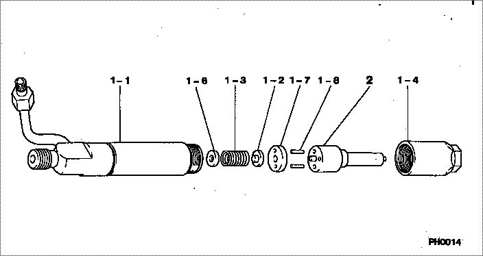
| 000. | [01] | 09350-03750 | HOLDER & NOZZLE SE | 36761-15060 |
| 001. | [01] | 09310-03750 | HOLDER ASSY, NOZZL | 36761-16600 |
| 001-001. | [01] | 09311-03750 | BODY SUB-ASSY, NOZ | |
| 001-002. | [01] | 09312-10390 | PIN, NOZZLE HOLDER | MM501786 |
| 001-003. | [01] | 09312-70350 | SPRING, NOZZLE HOL | MM501787 |
| 001-004. | [01] | 09316-41020 | NUT, NOZZLE RETAIN | MM501788 |
| 001-006. | [ C] | 09317-52570 | WASHER | |
| 001-006. | [ C] | 09317-52560 | WASHER | |
| 001-006. | [ C] | 09317-52530 | WASHER | |
| 001-006. | [ C] | 09317-52460 | WASHER | |
| 001-006. | [ C] | 09317-52450 | WASHER | |
| 001-006. | [ C] | 09317-52440 | WASHER | |
| 001-006. | [ C] | 09317-52430 | WASHER | |
| 001-006. | [ C] | 09317-52580 | WASHER | |
| 001-006. | [ C] | 09317-52590 | WASHER | |
| 001-006. | [ C] | 09317-52600 | WASHER | |
| 001-006. | [ C] | 09317-52610 | WASHER | |
| 001-006. | [ C] | 09317-52620 | WASHER | |
| 001-006. | [ C] | 09317-52630 | WASHER | |
| 001-006. | [ C] | 09317-52640 | WASHER | |
| 001-006. | [ C] | 09317-52650 | WASHER | |
| 001-006. | [ C] | 09317-52660 | WASHER | |
| 001-006. | [ C] | 09317-52420 | WASHER | |
| 001-006. | [ C] | 09317-52340 | WASHER | |
| 001-006. | [ C] | 09317-52180 | WASHER | |
| 001-006. | [ C] | 09317-52190 | WASHER | |
| 001-006. | [ C] | 09317-52200 | WASHER | |
| 001-006. | [ C] | 09317-52210 | WASHER | |
| 001-006. | [ C] | 09317-52220 | WASHER | |
| 001-006. | [ C] | 09317-52230 | WASHER | |
| 001-006. | [ C] | 09317-52240 | WASHER | |
| 001-006. | [ C] | 09317-52250 | WASHER | |
| 001-006. | [ C] | 09317-52260 | WASHER | |
| 001-006. | [ C] | 09317-52330 | WASHER | |
| 001-006. | [ C] | 09317-52320 | WASHER | |
| 001-006. | [ C] | 09317-52310 | WASHER | |
| 001-006. | [ C] | 09317-52300 | WASHER | MM501781 |
| 001-006. | [ C] | 09317-52290 | WASHER | |
| 001-006. | [ C] | 09317-52280 | WASHER | |
| 001-006. | [ C] | 09317-52270 | WASHER | |
| 001-007. | [01] | 09322-10090 | PACKING, TIP | MM501789 |
| 001-008. | [02] | 94908-23160 | PIN, STRAIGHT | MM501790 |
| 002. | [01] | 09340-05470 | NOZZLE ASSY | 36761-15600 |
Include in #3:
09350-03750
as HOLDER & NOZZLE SE
Cross reference number
| Part num | Firm num | Firm | Name |
| 09350-03750 | 36761-1506 | HOLDER & NOZZLE SE | |
| 36761-15060 | MITSUBISHI | HOLDER & NOZZLE SE |
Information:
P-501: Inspecting Electrical Connectors
Many of the Operational Procedures and Diagnostic Code Procedures in this troubleshooting guide will direct you to check a specific electrical connector.Use the following steps to help determine if the connector is the cause of the problem. If a problem is found in the electrical connector, repair the connector and continue the test procedure. 1. Check "DT" & "DRC" connector locking, and "HD" connector lock ring. Make sure that the connector is properly locked (clicked) together and that the two halves can't be pulled apart.2. Perform 10 pound pull test on each pin/wire. Each pin and connector should easily withstand 10 pounds of pull, and remain in the connector body. This test checks whether the wire was properly crimped in the pin, and whether the pin was properly inserted into the connector. The "DT" connectors use an orange wedge to lock the pins in place. Check to see that the orange wedge is not missing and installed properly on the "DT" connectors. Repair as needed. Pins should ALWAYS be crimped onto the wires; NEVER soldered. Use the Deutsch Crimp Tool (Cat P/N 1U5804).3. INSPECT CONNECTORS. Verify that pins and sockets are not corroded or damaged. Verify proper alignment and location of pins in the connector.4. CHECK INDIVIDUAL PIN AND SOCKET CONNECTIONS. This is especially important for intermittent problems. Using a new pin, insert the pin into each socket one at a time to check for a good grip on the pin by the socket. Repeat for each pin on the mating side of the connector, using a new socket for the test.P-510: Electrical Power Supply To The 3176 ECM Test
System Operation
The 3176 ECM receives electrical power (battery voltage) through wiring supplied by the vehicle manufacturer. In typical applications, 3176 receives power whenever the key is turned on.Some vehicles may be equipped with an engine protection shutdown system or an idle timer shutdown system (external to 3176) that interrupts electrical power to the ECM to shutdown the engine. Some of these will not supply power to 3176 until the engine is cranked, until oil pressure comes up to acceptable limits, or until an override button is pressed. Keep in mind that these devices may be the cause of intermittent power to the ECM.This procedure tests whether proper voltage is being supplied by vehicle wiring.For intermittent problems that could be caused by vehicle wiring (such as intermittent shutdowns) temporarily bypassing the vehicle wiring may be an effective means of determining the root cause. If symptoms vanish with the wiring bypassed, vehicle wiring was the cause. A means of bypassing vehicle wiring is explained in step 4 of the functional test. Schematic
Diagnostic Codes
Functional Test
Illustration 3P-511: Throttle Position Circuit Test And Calibration
System Operation
The throttle position sensor is used to provide a throttle signal to the ECM. Sensor output is a constant frequency signal with a pulse width that varies with throttle position. This output signal is referred to as either "Duty Cycle" or a "Pulse Width Modulated" (PWM) signal