Information holder & nozzle se
Rating:
Components :
| 001. | HOLDER & NOZZLE SE | 09350-03610 |
Scheme ###:
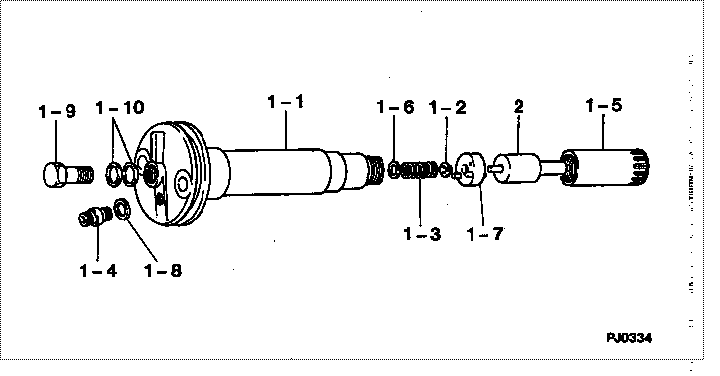
| 000. | [01] | 09350-03610 | HOLDER & NOZZLE SE | 61511-13300 |
| 001. | [01] | 09310-03610 | HOLDER ASSY, NOZZL | 61511-13310 |
| 001-001. | [01] | 09311-03610 | BODY SUB-ASSY, NOZ | |
| 001-002. | [01] | 09312-10320 | PIN, NOZZLE HOLDER | |
| 001-003. | [01] | 09312-70270 | SPRING, NOZZLE HOL | |
| 001-004. | [01] | 09315-10390 | CONNECTOR, NOZZLE | |
| 001-005. | [01] | 09316-41180 | NUT, NOZZLE RETAIN | |
| 001-006. | [ C] | 09317-51620 | WASHER | |
| 001-006. | [ C] | 09317-51610 | WASHER | |
| 001-006. | [ C] | 09317-51600 | WASHER | |
| 001-006. | [ C] | 09317-51590 | WASHER | |
| 001-006. | [ C] | 09317-51580 | WASHER | |
| 001-006. | [ C] | 09317-51570 | WASHER | |
| 001-006. | [ C] | 09317-51560 | WASHER | |
| 001-006. | [ C] | 09317-51550 | WASHER | |
| 001-006. | [ C] | 09317-51630 | WASHER | |
| 001-006. | [ C] | 09317-51640 | WASHER | |
| 001-006. | [ C] | 09317-51650 | WASHER | |
| 001-006. | [ C] | 09317-53950 | WASHER | |
| 001-006. | [ C] | 09317-53940 | WASHER | |
| 001-006. | [ C] | 09317-53930 | WASHER | |
| 001-006. | [ C] | 09317-53920 | WASHER | |
| 001-006. | [ C] | 09317-53910 | WASHER | |
| 001-006. | [ C] | 09317-53900 | WASHER | |
| 001-006. | [ C] | 09317-53890 | WASHER | |
| 001-006. | [ C] | 09317-53880 | WASHER | |
| 001-006. | [ C] | 09317-51540 | WASHER | |
| 001-006. | [ C] | 09317-51530 | WASHER | |
| 001-006. | [ C] | 09317-51520 | WASHER | |
| 001-006. | [ C] | 09317-51090 | WASHER | |
| 001-006. | [ C] | 09317-51080 | WASHER | |
| 001-006. | [ C] | 09317-51070 | WASHER | |
| 001-006. | [ C] | 09317-51060 | WASHER | |
| 001-006. | [ C] | 09317-51050 | WASHER | |
| 001-006. | [ C] | 09317-51040 | WASHER | |
| 001-006. | [ C] | 09317-51030 | WASHER | |
| 001-006. | [ C] | 09317-51020 | WASHER | |
| 001-006. | [ C] | 09317-51100 | WASHER | |
| 001-006. | [ C] | 09317-51110 | WASHER | |
| 001-006. | [ C] | 09317-51120 | WASHER | |
| 001-006. | [ C] | 09317-51510 | WASHER | |
| 001-006. | [ C] | 09317-51500 | WASHER | |
| 001-006. | [ C] | 09317-51180 | WASHER | |
| 001-006. | [ C] | 09317-51170 | WASHER | |
| 001-006. | [ C] | 09317-51160 | WASHER | |
| 001-006. | [ C] | 09317-51150 | WASHER | |
| 001-006. | [ C] | 09317-51140 | WASHER | |
| 001-006. | [ C] | 09317-51130 | WASHER | |
| 001-007. | [01] | 09322-00050 | PACKING SUB-ASSY, | |
| 001-008. | [01] | 09315-80010 | GASKET, INLET CONN | 09315-80010 |
| 001-009. | [01] | 09316-60010 | SCREW, HOLLOW | 09316-60010 |
| 001-010. | [02] | 09022-20080 | WASHER, FUEL PIPE | 09022-20080 |
| 002. | [01] | 09340-01600 | NOZZLE ASSY | 61501-13120 |
Include in #3:
09350-03610
as HOLDER & NOZZLE SE
Include as Nozzle:
1910003340
as Nozzle
Cross reference number
| Part num | Firm num | Firm | Name |
| 09350-03610 | 61511-1330 | HOLDER & NOZZLE SE | |
| 61511-13300 | KOMATSU | HOLDER & NOZZLE SE |
Information:
(4) Spacer block.(5) Height of dowels above top surface of spacer block and cylinder block ... 8.00 0.03 mm (.315 .001 in)(6) Cylinder Liner. Make reference to the procedure for checking Cylinder Liner Projection in Testing And Adjusting Section of Service Manual Form No. SENR5108. Cylinder liner projection above the top surface of the spacer block must be ... 0.12 0.08 mm (.005 .003 in) Apply 7M7260 Liquid Gasket as required to cylinder liner shoulder and cylinder block face joint of all liners. (7) Depth plug is to be installed (from end surface of cylinder block to top of plug) ... 1.25 0.25 mm (.049 .010 in)(8) Diameter of camshaft bores ... 75.000 0.025 mm (2.9530 .0010 in)(9) Oil cooling jet assembly. Tighten bolt that holds oil cooling jet to ... 25 7 N m (18 5 1b ft)(10) Width of main bearing cap ... 175.00 0.02 mm (6.8898 .0008 in) Width in cylinder block for main bearing cap ... 175.000 0.018 mm (6.8898 .0007 in)(11) Distance from centerline of crankshaft bore to top surface of cylinder block ... 265.0 mm (10.43 in)The flatness across the top contact surface of the block must be within 0.05 mm (.002 in) for any 150 mm (5.9 in) section of the surface.(12) Distance from centerline of crankshaft to bottom surface of cylinder block ... 120.0 mm (4.72 in)(13) Main bearing cap bolts. Install as follows: Main bearing caps shall be assembled with the part number towards the right side. Caps are to be identified by stamped numbers 1 thru 7 located on the bottom unmachined surface.Main bearing cap bolts to be lubricated on threads and washer face with SAE 30 oil or molylube. Tighten bolts to 95 5 N m (70 4 lb ft) plus 90 5° additional turn prior to machining. Tighten bolts simultaneously or tighten both bolts to 95 N m (70 lb ft) before turning the additional 90°.(14) Bore in cylinder block for seven main bearings ... 108.000 0.013 mm (4.2520 .0005 in) All main bearing bore measurements are to be made before caps are disassembled.