Information holder & nozzle se
Rating:
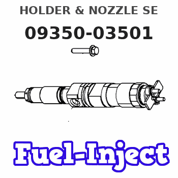
Components :
| 001. | HOLDER & NOZZLE SE | 09350-03501 |
| 001. | HOLDER & NOZZLE SE | 09350-03501 |
Scheme ###:

| 000. | [01] | 09350-03501 | HOLDER & NOZZLE SE | 23610-1512 |
| 000. | [01] | 09350-03501 | HOLDER & NOZZLE SE | S2361-01512 |
| 001. | [01] | 09310-03501 | HOLDER ASSY, NOZZL | S2363-01461-A |
| 001. | [01] | 09310-03501 | HOLDER ASSY, NOZZL | S2363-01461-A |
| 001-001. | [01] | 09311-03501 | BODY SUB-ASSY, NOZ | |
| 001-002. | [01] | 09312-10330 | PIN, NOZZLE HOLDER | S2361-61030-A |
| 001-003. | [01] | 09312-70280 | SPRING, NOZZLE HOL | S2361-51190-A |
| 001-004. | [01] | 09313-10200 | SCREW, ADJUST | S2361-41060-A |
| 001-005. | [01] | 09313-40270 | NUT, CAP | S2362-31310-A |
| 001-006. | [01] | 09315-10340 | CONNECTOR, NOZZLE | 23611-1190A |
| 001-007. | [01] | 09315-80010 | GASKET, INLET CONN | S2362-11070-A |
| 001-008. | [01] | 09316-41240 | NUT, NOZZLE RETAIN | S2363-31320-A |
| 001-009. | [01] | 94918-00630 | SCREW, HOLLOW | S2283-51130-A |
| 001-009. | [01] | 09507-40012 | SCREW, HOLLOW OUTL | S2283-51570-A |
| 001-010. | [01] | 09324-50052 | WASHER | S2284-71290-A |
| 001-011. | [02] | 94901-02640 | WASHER | S2284-71870-A |
| 002. | [01] | 09340-02002 | NOZZLE ASSY | S2365-01471-A |
Include in #3:
09350-03501
as HOLDER & NOZZLE SE
09350-03501
Cross reference number
| Part num | Firm num | Firm | Name |
| 09350-03501 | 23610-1512 | HOLDER & NOZZLE SE |
Information:
1. Disconnect water supply hose from water pump inlet.2. Remove connector pipe (1), remove two bolts (2) and remove oil fill pipe (3). 3. Remove bolts (4) and (5) then remove the water pump. The following steps are for the installation of the water pump.4. Position the water pump and install two bolts (5) and (6). Tighten the two bolts evenly.5. Position connector pipe (1) and gaskets then install the bolts.6. Install oil fill pipe (3). Be sure the gasket is in position between the regulator and pipe and install bolts (2).End By:a. Install alternator (if removed)b. Fill the cooling system to the specified level. See the Maintenance Manual.Disassemble And Assemble Water Pump
Start By:a. remove water pump 1. Remove three bolts (1) and remove cover (2). 2. Use an M12 X 1.75 bolt to force impeller (3) from shaft (4). Install forcing bolt in impeller as indicated by arrow. Hold impeller and screw bolt in until impeller comes off shaft. 3. Remove bolt (5), washer (6), bearing (7) and gear (8). 4. Remove three bolts (9) and remove cover (10) with bearing (11). 5. Press shaft (4) out of seal (12).
Do not allow shaft (4) to fall to the floor, damage may occur to the shaft.
6. Remove seal (12) and seal (13) from water pump housing. The following steps are for the assembly of the water pump. 7. Using driver group, install seal (13). Refer to illustration to see direction of seal lip. Lubricate shaft seal area with engine oil.8. Assemble shaft (4), bearing (11) and cover (10). Position assembly into seal and housing then install bolts (9). 9. Position the housing and shaft assembly in a press. Position seal (12) on shaft (4). 10. Position tool (A) and press seal into place. 11. Position the water pump in a press, position impeller (3) and press it into place. Dimension X is 1.5 0.5 mm (.059 .020 in.).12. Position seal and cover (2), then install bolts (1).End By:a. install water pump