Information holder & nozzle se

Rating:
Components :
| 001. | HOLDER & NOZZLE SE | 09350-03260 |
Scheme ###:
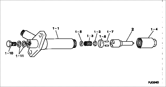
| 000. | [01] | 09350-03260 | HOLDER & NOZZLE SE | 23600-68030 |
| 001. | [01] | 09310-03260 | HOLDER ASSY, NOZZL | 23610-68030 |
| 001-001. | [01] | 09311-03260 | BODY SUB-ASSY, NOZ | 23626-68030 |
| 001-002. | [01] | 09312-10390 | PIN, NOZZLE HOLDER | |
| 001-003. | [01] | 09312-70350 | SPRING, NOZZLE HOL | |
| 001-004. | [01] | 09316-41020 | NUT, NOZZLE RETAIN | 23624-58010 |
| 001-005. | [ C] | 09317-52570 | WASHER | 23633-58014 |
| 001-005. | [ C] | 09317-52560 | WASHER | 23633-58013 |
| 001-005. | [ C] | 09317-52530 | WASHER | 23633-58012 |
| 001-005. | [ C] | 09317-52460 | WASHER | 23633-58011 |
| 001-005. | [ C] | 09317-52450 | WASHER | 23633-58010 |
| 001-005. | [ C] | 09317-52440 | WASHER | 23632-58019 |
| 001-005. | [ C] | 09317-52430 | WASHER | 23632-58018 |
| 001-005. | [ C] | 09317-52580 | WASHER | 23633-58015 |
| 001-005. | [ C] | 09317-52590 | WASHER | 23633-58016 |
| 001-005. | [ C] | 09317-52600 | WASHER | 23633-58017 |
| 001-005. | [ C] | 09317-52610 | WASHER | 23633-58018 |
| 001-005. | [ C] | 09317-52620 | WASHER | 23633-58019 |
| 001-005. | [ C] | 09317-52630 | WASHER | 23634-58010 |
| 001-005. | [ C] | 09317-52640 | WASHER | 23634-58011 |
| 001-005. | [ C] | 09317-52650 | WASHER | 23634-58012 |
| 001-005. | [ C] | 09317-52660 | WASHER | 23634-58013 |
| 001-005. | [ C] | 09317-52420 | WASHER | 23632-58017 |
| 001-005. | [ C] | 09317-52340 | WASHER | 23632-58016 |
| 001-005. | [ C] | 09317-52180 | WASHER | 23631-58010 |
| 001-005. | [ C] | 09317-52190 | WASHER | 23631-58011 |
| 001-005. | [ C] | 09317-52200 | WASHER | 23631-58012 |
| 001-005. | [ C] | 09317-52210 | WASHER | 23631-58013 |
| 001-005. | [ C] | 09317-52220 | WASHER | 23631-58014 |
| 001-005. | [ C] | 09317-52230 | WASHER | 23631-58015 |
| 001-005. | [ C] | 09317-52240 | WASHER | 23631-58016 |
| 001-005. | [ C] | 09317-52250 | WASHER | 23631-58017 |
| 001-005. | [ C] | 09317-52260 | WASHER | 23631-58018 |
| 001-005. | [ C] | 09317-52330 | WASHER | 23632-58015 |
| 001-005. | [ C] | 09317-52320 | WASHER | 23632-58014 |
| 001-005. | [ C] | 09317-52310 | WASHER | 23632-58013 |
| 001-005. | [ C] | 09317-52300 | WASHER | 23632-58012 |
| 001-005. | [ C] | 09317-52290 | WASHER | 23632-58011 |
| 001-005. | [ C] | 09317-52280 | WASHER | 23632-58010 |
| 001-005. | [ C] | 09317-52270 | WASHER | 23631-58019 |
| 001-006. | [01] | 09322-10090 | PACKING, TIP | |
| 001-007. | [02] | 94908-23160 | PIN, STRAIGHT | 90099-08096 |
| 001-010. | [01] | 09316-60080 | SCREW, HOLLOW | 23625-58230 |
| 001-011. | [02] | 94901-81020 | WASHER, COPPER PLA | 90201-08106 |
| 002. | [01] | 09340-05240 | NOZZLE ASSY | 23620-68030 |
Include in #3:
09350-03260
as HOLDER & NOZZLE SE
Include as Nozzle:
Cross reference number
| Part num | Firm num | Firm | Name |
| 09350-03260 | 23600-6803 | HOLDER & NOZZLE SE | |
| 23600-68030 | TOYOTA | HOLDER & NOZZLE SE |
Information:
Required Equipment
The following is a list of equipment required to test and calibrate pressure contactors.* 6V-7070 Multimeter or Equivalent A multimeter is used to verify the actuation and deactuation settings. This is done by checking for continuity between two terminals inside the contactor.* Air Compressor and Pressure Regulator An air source is used to supply the air pressure to the contactor. Make sure the maximum obtainable air supply is slightly greater than the pressure required to set the actuation pressure setting. The pressure regulator allows the pressure to be gradually increased or decreased to the specified pressure.Calibration Procedure for Model KPS 35 and KPS 37 Contactors
Use the following procedure to check and calibrate pressure contactor models KPS 35 and KPS 37.1. If connected, disconnect the contactor from the power supply. Mark terminal locations and disconnect the three wires from terminals 1, 2, and 4.
High voltage electrical shock is possible. The contactor must be disconnected from the power supply and the wires disconnected from terminals 1, 2, and 4. Failure to follow this recommendation can result in serious bodily injury.
2. Locate and record the part number of the pressure contactor in Chart A. Using the part number and Chart A, determine the actuation and deactuation pressures. Verify that the contactor being tested is a model KPS 35 or KPS 37. If not, refer to the procedure for the specific model of pressure contactor being tested.
Pressure Contactor
(1) Housing cover. (2) Housing cover screws. (3) Pressure port.3. Loosen housing cover screws (2) as shown and remove housing cover (1).4. Connect the air supply to the pressure port (3). The air pressure regulator should be set to zero.
Nomenclature For Internal Parts
(4) Lock screw. (5) Range spindle. (6) Range scale. (7) Differential spindle. (8) Differential scale.5. Loosen lock screw (4).6. Adjust range spindle (5) to a setting above the desired actuation setting determined in Step 2. Determine the setting by using range scale (6).7. Adjust differential spindle (7) using differential scale (8) to the approximate mechanical differential pressure. Mechanical differential pressure is the difference between the actuation and deactuation pressures.
Pressure Control Function For Actuation And Deactuation Of Models KPS 35 (specifically shown for the 4W-2642 Contactor) And KPS 37
Adjusting Pressure And Differential Settings On A 4W-2642 (KPS 35) Pressure Contactor
This example shows the pressure set at 38 psi with a 7 psi mechanical differential pressure setting. This results in an actuation pressure of 45 psi and deactuation pressure of 38 psi. Refer to the "Pressure Control Function For Actuation And Deactuation Of Models KPS 35 And KPS 37" illustration.8. Increase the air supply to the desired actuation pressure.9. When the actuation pressure has stabilized, very slowly turn range spindle (5) counterclockwise until the contact actuates. This will be accompanied by an audible "click".
When Contact Actuates, Terminals 1 And 4 Will Have Continuity10. Use a 6V-7070 Multimeter, or equivalent, to verify the actuation of the contactor. Check for continuity between terminals 1 and 4. If there is no continuity, the contactor has not actuated;