Information holder & nozzle se
Rating:
Components :
| 001. | HOLDER & NOZZLE SE | 09350-03140 |
Scheme ###:
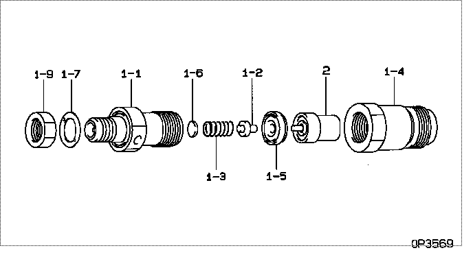
| 000. | [01] | 09350-03140 | HOLDER & NOZZLE SE | 131406310 |
| 001. | [01] | 09310-03140 | HOLDER ASSY, NOZZL | |
| 001-001. | [01] | 09311-03140 | BODY SUB-ASSY, NOZ | |
| 001-002. | [01] | 09312-10030 | PIN, NOZZLE HOLDER | 131446012 |
| 001-003. | [01] | 09312-70020 | SPRING, NOZZLE HOL | 131446011 |
| 001-004. | [01] | 09316-40691 | NUT, NOZZLE RETAIN | 131446064 |
| 001-005. | [01] | 09317-40011 | DISTANCE PIECE | 131446058 |
| 001-006. | [1C] | 09317-50120 | WASHER | 131436650 |
| 001-006. | [1C] | 09317-50130 | WASHER | 131436660 |
| 001-006. | [1C] | 09317-50140 | WASHER | 131436670 |
| 001-006. | [1C] | 09317-50150 | WASHER | 131436680 |
| 001-006. | [1C] | 09317-50160 | WASHER | 131436690 |
| 001-006. | [1C] | 09317-50170 | WASHER | 131436700 |
| 001-006. | [1C] | 09317-50180 | WASHER | 131436710 |
| 001-006. | [1C] | 09317-50190 | WASHER | 131436720 |
| 001-006. | [1C] | 09317-50200 | WASHER | 131436730 |
| 001-006. | [1C] | 09317-50110 | WASHER | 131436640 |
| 001-006. | [1C] | 09317-50100 | WASHER | 131436630 |
| 001-006. | [1C] | 09317-50010 | WASHER | 131436540 |
| 001-006. | [1C] | 09317-50020 | WASHER | 131436550 |
| 001-006. | [1C] | 09317-50030 | WASHER | 131436560 |
| 001-006. | [1C] | 09317-50040 | WASHER | 131436570 |
| 001-006. | [1C] | 09317-50050 | WASHER | 131436580 |
| 001-006. | [1C] | 09317-50060 | WASHER | 131436590 |
| 001-006. | [1C] | 09317-50070 | WASHER | 131436600 |
| 001-006. | [1C] | 09317-50080 | WASHER | 131436610 |
| 001-006. | [1C] | 09317-50090 | WASHER | 131436620 |
| 001-007. | [01] | 09324-50040 | WASHER | 131426120 |
| 001-009. | [01] | 94905-02480 | NUT, HEXAGON | 131446008 |
| 002. | [01] | 09340-01480 | NOZZLE ASSY | 131416120 |
Include in #3:
09350-03140
as HOLDER & NOZZLE SE
Cross reference number
| Part num | Firm num | Firm | Name |
| 09350-03140 | 131406310 | HOLDER & NOZZLE SE | |
| 131406310 | ISHIKAWAJIMA | HOLDER & NOZZLE SE |
Information:
The following information given is for repair only of the indicator. Basic troubleshooting information for the complete group is given in Special Instruction Form SEHS7742, "Service Information and Use of 6V3100 Diesel Engine Timing Indicator Group".Operation Of System
The 6V3100 Diesel Engine Timing Indicator Group measures fuel injection timing while the engine is in operation by finding at what degree BTC (before top center) that fuel is injected into number one cylinder. It makes a comparison with TC (top center), and the difference in time between these two points is measured and read out in degrees BTC. The pressure transducer monitors the fuel line pressure and provides an output that is calibrated for a predetermined pressure. When the fuel line pressure reaches this predetermined value of 6895 kPa (1,000 psi), the pressure transducer signals the indicator to start measuring time. The engine continues to rotate to top center, where the TDC transducer (magnetic pickup) outputs a signal corresponding to engine TC. This signal is generated by sensing the location of the static timing pin hole (located in flywheel or timing gear, depending upon the engine model). At this instant, the indicator stops measuring time and gives the number of crankshaft degrees between full injection and top center on the DEG display.Block Diagram - 6V3100
Circuit Operation
R/MIN Readout
6V2192 Injection Transducer - The 6V2192 has a differential output between connector pins J301-4 and J301-2 (see 6V3100 INDICATOR SCHEMATIC insert). At a fuel line pressure of 6895 kPa (1,000 psi), J301-4 is zero Volts with respect to J301-2. Increasing the pressure causes J301-4 to "crossover" from negative to positive with respect to J301-2. When this happens, the output of IC301B, TP13, goes low. Alternate Pressure Transducers - Other types of pressure transducers may be used to sense injection if their outputs equal 2.830 Volts at 6895 kPa (1,000 psi). Because J301-2 is adjusted to 2.830 Volts positive with respect to ground (J301-3), any input on J301-4 that crosses through (from negative to positive) 2.830 Volts with respect to J301-3 will also cause the output of IC301B, TP13, to go low.IC301A is a zero crossing detector. Its output switches (changes state) every time that J301-4 crosses through zero Volts with respect to J301-2. TP13 goes low (-5V) every time the injection pressure in line number one gets to 6985 kPa (1,000 psi) and returns high (+8 V) at the end of each injection pulse. When TP13 goes low, it clocks (triggers) the 23 ms Monostable, IC302A, so its output TP14, goes high. This output serves two purposes.1) Switches (changes state) the output of DEG Flip-Flop, TP20, high.2) Input signal for R/Min Limiter.The R/Min Limiter output, TP16, goes high with TP14 but TP16 amplitude is a precision 5 Volts as determined by REG102. TP16 stays high until 23 ms Monostable IC302A times out. So, TP16 is then a series of constant amplitude, constant duration pulses whose repetition rate is proportional to engine speed. One pulse is generated on TP16 for each fuel pulse.The R/Min Filter,