Information holder & nozzle se
Rating:
Components :
| 001. | HOLDER & NOZZLE SE | 09350-02720 |
| 001. | HOLDER & NOZZLE SE | 09350-02720 |
Scheme ###:
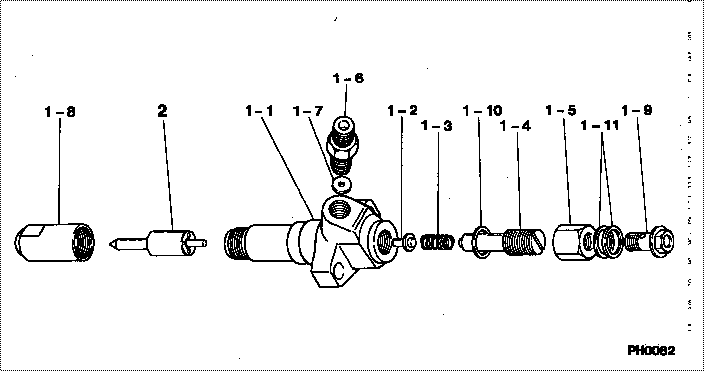
| 000. | [01] | 09350-02720 | HOLDER & NOZZLE SE | 23610-1412 |
| 000. | [01] | 09350-02720 | HOLDER & NOZZLE SE | S2361-01412 |
| 001. | [01] | 09310-02720 | HOLDER ASSY, NOZZL | 23630-1341A |
| 001-001. | [01] | 09311-02720 | BODY SUB-ASSY, NOZ | 23602-1340A |
| 001-002. | [01] | 09312-10330 | PIN, NOZZLE HOLDER | S2361-61030-A |
| 001-003. | [01] | 09312-70280 | SPRING, NOZZLE HOL | S2361-51190-A |
| 001-004. | [01] | 09313-10200 | SCREW, ADJUST | S2361-41060-A |
| 001-005. | [01] | 09313-40270 | NUT, CAP | S2362-31310-A |
| 001-005. | [01] | 09313-40330 | NUT, CAP | 23623-1110 |
| 001-006. | [01] | 09315-10340 | CONNECTOR, NOZZLE | 23611-1190A |
| 001-007. | [01] | 09315-80010 | GASKET, INLET CONN | S2362-11070-A |
| 001-008. | [01] | 09316-40830 | NUT, NOZZLE RETAIN | 23633-1030 |
| 001-009. | [01] | 94918-00630 | SCREW, HOLLOW | S2283-51130-A |
| 001-009. | [01] | 09507-40012 | SCREW, HOLLOW OUTL | S2283-51570-A |
| 001-010. | [01] | 09324-50052 | WASHER | S2284-71290-A |
| 001-011. | [02] | 94901-02640 | WASHER | S2284-71870-A |
| 002. | [01] | 09340-01590 | NOZZLE ASSY | S2365-01331-A |
Include in #3:
09350-02720
as HOLDER & NOZZLE SE
09350-02720
Cross reference number
| Part num | Firm num | Firm | Name |
| 09350-02720 | 23610-1412 | HOLDER & NOZZLE SE | |
| 23610-1412 | HINO | HOLDER & NOZZLE SE | |
| S2361-01412 | HINO | HOLDER & NOZZLE SE |
Information:
Emergency Stopping
Emergency shutoff controls are for EMERGENCY use ONLY. DO NOT use emergency shutoff devices or controls for normal stopping procedure.
Make sure that any external system components that have been operating to support engine operation are secured after any stop.Emergency Stop Button
Emergency stop button, mounted on a junction box.Emergency stops may be made by pushing the Emergency Stop Button located on the junction box (if equipped). Both the button and the air inlet shutoff (if equipped) require resetting before the engine will start.Air Shutoff (If Equipped)
Some engines are equipped with an air shutoff, located between the aftercooler and the turbocharger. If equipped with an air shutoff lever, move the lever to the OFF position.Manual Stop Procedure
Stopping the engine immediately after it has been working under load, can result in overheating and accelerated wear of the engine components. Follow the stopping procedure, outlined below, to allow the engine to cool. Excessive temperatures in the turbocharger center housing will cause oil coking problems. Shutting the engine off without a cool down period does not allow the coolant temperature to stabilize, and may result in exhaust manifold cracking or leaking. Follow the stopping procedure outlined below to allow the engine to cool before shut down.
There may be several ways to shut off your engine. Make sure the shutoff procedures are understood. Use the following general guidelines for stopping the engine.1. Reduce engine speed to low idle.2. Shift into NEUTRAL.3. If the engine has been operated at low loads, run the engine at LOW IDLE for 30 seconds before stopping.If the engine has been operated at high load, increase engine speed to no more than 1/2 rated speed for three to five minutes to reduce and stabilize internal engine coolant and oil temperatures. Then reduce the engine speed to low idle before stopping.4. Check the marine transmission oil level while the engine is idling. Refer to the marine transmission OEM literature for lubrication maintenance recommendations.5. Follow your vessel's OEM instructions for stopping the engine with the pilot controls.A manual shutoff shaft is provided to override the governor control. The shaft can be used to move the fuel control linkage to the FUEL OFF position. The engine may be stopped by using the shaft and the mechanical governor control (if equipped).
Typical mechanical governor control.Move the mechanical governor control to the FUEL OFF position. Hold the control at the FUEL OFF position until the engine stops.After Stopping the Engine
Check the crankcase oil level. Maintain the oil level between the ADD and FULL marks on the dipstick.Repair any leaks, perform minor adjustments, tighten loose bolts, etc.Note the service hour meter reading. Perform periodic maintenance as instructed in the Maintenance Schedule.Fill the fuel tank to prevent accumulation of moisture in the fuel. Do not overfill.
Only use antifreeze/coolant mixtures recommended in the Cooling System Specifications of this manual. Failure to do so can cause engine damage.
Allow the engine to cool. Check the coolant level. Maintain the cooling system to 13 mm (1/2 inch) from bottom of the