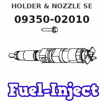
Information holder & nozzle se
Rating:
Compare Prices: .
As an associate, we earn commssions on qualifying purchases through the links below

$151.69
19 Feb 2024
CN: GEMMOE
Pcs Fuel Injector Assy Model 093500-2010 23600-87304-000 for Daihatsu Engine DL
Thcbme Part Number: 093500-2010 || Application: For Daihatsu Engine DL??????? || Ideal replacement: Precision engineered to match specific vehicles || Ensure fit: To make sure this part fits your exact vehicle. || Ensure fit: To make sure this part fits your exact vehicle.
Thcbme Part Number: 093500-2010 || Application: For Daihatsu Engine DL??????? || Ideal replacement: Precision engineered to match specific vehicles || Ensure fit: To make sure this part fits your exact vehicle. || Ensure fit: To make sure this part fits your exact vehicle.

$168.00
07 Jan 2024
CN: YZMZONPARTS
YZMZONPARTS 4PCS Fuel Injector Assy 093500-2010 23600-87304-000 compatible with Daihatsu DL
HOLDWELL Part Number: 093500-2010 23600-87304-000 0935002010 2360087304000 || 093500-2010 23600-87304-000 0935002010 2360087304000 Fuel Injector || Compatible with Daihatsu DL || Package Includes: Fuel Injector x 4 || New Aftermarket
HOLDWELL Part Number: 093500-2010 23600-87304-000 0935002010 2360087304000 || 093500-2010 23600-87304-000 0935002010 2360087304000 Fuel Injector || Compatible with Daihatsu DL || Package Includes: Fuel Injector x 4 || New Aftermarket

$153.48
12 Dec 2023
CN: QYWD
23600-87304-000 093500-2010 Pcs Fuel Injector Assy for Daihatsu Engine DL
TUWODE Part Number: 093500-2010 || Part Name:Fuel Injector || Application: Compatible with Daihatsu Engine DL??????? || Installation is straightforward and does not necessitate any commissioning. || Consumes less fuel and prolongs the service life.
TUWODE Part Number: 093500-2010 || Part Name:Fuel Injector || Application: Compatible with Daihatsu Engine DL??????? || Installation is straightforward and does not necessitate any commissioning. || Consumes less fuel and prolongs the service life.
Components :
| 001. | HOLDER & NOZZLE SE | 09350-02010 |
| 001. | HOLDER & NOZZLE SE | 09350-02010 |
Scheme ###:
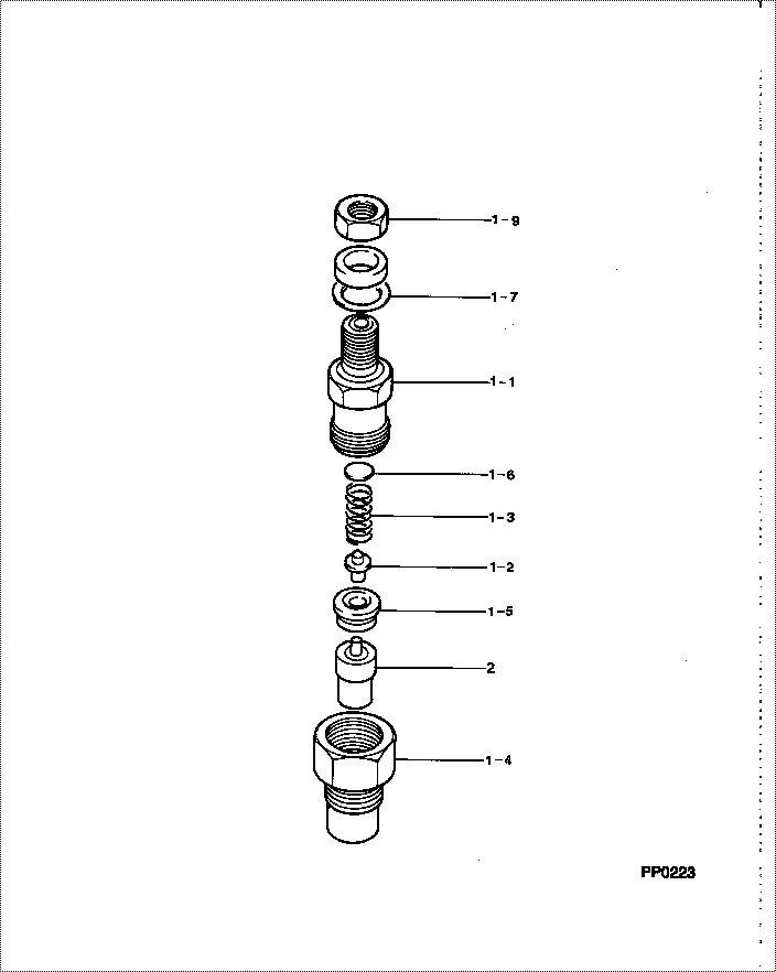
| 000. | [01] | 09350-02010 | HOLDER & NOZZLE SE | 23600-87304-000 |
| 000. | [01] | 09350-02010 | HOLDER & NOZZLE SE | 2360A-87304 |
| 001. | [01] | 09310-02010 | HOLDER ASSY, NOZZL | |
| 001. | [01] | 09310-02010 | HOLDER ASSY, NOZZL | 23610-87304-000 |
| 001-001. | [01] | 09311-02010 | BODY SUB-ASSY, NOZ | 23626-87302-000 |
| 001-001. | [01] | 09311-02010 | BODY SUB-ASSY, NOZ | |
| 001-002. | [01] | 09312-10030 | PIN, NOZZLE HOLDER | 23619-46010-000 |
| 001-002. | [01] | 09312-10030 | PIN, NOZZLE HOLDER | 0 931 2100 30 |
| 001-003. | [01] | 09312-70020 | SPRING, NOZZLE HOL | 23618-46010-000 |
| 001-003. | [01] | 09312-70020 | SPRING, NOZZLE HOL | 6 303 1700 20 |
| 001-004. | [01] | 09316-41140 | NUT, NOZZLE RETAIN | |
| 001-004. | [01] | 09316-40172 | NUT, NOZZLE RETAIN | |
| 001-004. | [01] | 09316-41140 | NUT, NOZZLE RETAIN | |
| 001-004. | [01] | 09316-40172 | NUT, NOZZLE RETAIN | |
| 001-005. | [01] | 09317-40011 | DISTANCE PIECE | 6 056 1700 20 |
| 001-005. | [01] | 09317-40011 | DISTANCE PIECE | 23629-46010-000 |
| 001-006. | [1C] | 09317-50080 | WASHER | 2363J-46010 |
| 001-006. | [1C] | 09317-50070 | WASHER | 2363H-46010 |
| 001-006. | [1C] | 09317-50060 | WASHER | 2363G-46010 |
| 001-006. | [1C] | 09317-50050 | WASHER | 2363F-46010 |
| 001-006. | [1C] | 09317-50040 | WASHER | 2363E-46010 |
| 001-006. | [1C] | 09317-50030 | WASHER | 2363D-46010 |
| 001-006. | [1C] | 09317-50020 | WASHER | 0 931 7500 20 |
| 001-006. | [1C] | 09317-50010 | WASHER | 2363B-46010 |
| 001-006. | [1C] | 09317-50170 | WASHER | 23648-46010-000 |
| 001-006. | [1C] | 09317-50090 | WASHER | 2363K-46010 |
| 001-006. | [1C] | 09317-50100 | WASHER | 2364B-46010 |
| 001-006. | [1C] | 09317-50190 | WASHER | 2365B-46010 |
| 001-006. | [1C] | 09317-50180 | WASHER | 2364K-46010 |
| 001-006. | [1C] | 09317-50170 | WASHER | 2364J-46010 |
| 001-006. | [1C] | 09317-50160 | WASHER | 2364H-46010 |
| 001-006. | [1C] | 09317-50150 | WASHER | 2364G-46010 |
| 001-006. | [1C] | 09317-50140 | WASHER | 2364F-46010 |
| 001-006. | [1C] | 09317-50130 | WASHER | 2364E-46010 |
| 001-006. | [1C] | 09317-50120 | WASHER | 2364D-46010 |
| 001-006. | [1C] | 09317-50110 | WASHER | 2364C-46010 |
| 001-006. | [1C] | 09317-50200 | WASHER | 22881-2520 |
| 001-006. | [1C] | 09317-50010 | WASHER | 23631-46010-000 |
| 001-006. | [1C] | 09317-50160 | WASHER | 23647-46010-000 |
| 001-006. | [1C] | 09317-50150 | WASHER | 23646-46010-000 |
| 001-006. | [1C] | 09317-50140 | WASHER | 23645-46010-000 |
| 001-006. | [1C] | 09317-50130 | WASHER | 23644-46010-000 |
| 001-006. | [1C] | 09317-50120 | WASHER | 23643-46010-000 |
| 001-006. | [1C] | 09317-50110 | WASHER | 23642-46010-000 |
| 001-006. | [1C] | 09317-50100 | WASHER | 23641-46010-000 |
| 001-006. | [1C] | 09317-50090 | WASHER | 23639-46010-000 |
| 001-006. | [1C] | 09317-50080 | WASHER | 23638-46010-000 |
| 001-006. | [1C] | 09317-50070 | WASHER | 23637-46010-000 |
| 001-006. | [1C] | 09317-50180 | WASHER | 23649-46010-000 |
| 001-006. | [1C] | 09317-50190 | WASHER | 23651-46010-000 |
| 001-006. | [1C] | 09317-50020 | WASHER | 23632-46010-000 |
| 001-006. | [1C] | 09317-50030 | WASHER | 23633-46010-000 |
| 001-006. | [1C] | 09317-50040 | WASHER | 23634-46010-000 |
| 001-006. | [1C] | 09317-50050 | WASHER | 23635-46010-000 |
| 001-006. | [1C] | 09317-50060 | WASHER | 23636-46010-000 |
| 001-006. | [1C] | 09317-50200 | WASHER | 23652-46010-000 |
| 001-007. | [01] | 09324-50040 | WASHER | 23654-46010-000 |
| 001-007. | [01] | 09324-50040 | WASHER | 0 932 4500 40 |
| 001-009. | [01] | 94905-02480 | NUT, HEXAGON | 23628-46010-000 |
| 001-009. | [01] | 94905-02480 | NUT, HEXAGON | 9 490 5024 80 |
| 002. | [01] | 09340-00950 | NOZZLE ASSY | 23620-87302-000 |
| 002. | [01] | 09340-00950 | NOZZLE ASSY | 2362A-87302 |
Include in #3:
09350-02010
as HOLDER & NOZZLE SE
09350-02010
Cross reference number
| Part num | Firm num | Firm | Name |
| 09350-02010 | 23600-8730 | HOLDER & NOZZLE SE | |
| 2360A-87304 | HINO | HOLDER & NOZZLE SE | |
| 23600-87304-000 | DAIHATSU | HOLDER & NOZZLE SE |
Information:
2. Remove bolts (1) from the alternator bracket.3. Remove the bolts that hold plate (3), and remove the plate.4. Disconnect water line (2) from the air compressor. Turn the water line tee toward the lifting bracket in order to provide clearance to remove the head bolt. 5. Remove bolts (4) and (5) that hold the cylinder head assembly to the cylinder block.6. Fasten a hoist, and remove the cylinder head assembly. The weight is approximately 135 kg (300 lb.).
Do not put the cylinder head assembly down on a flat surface. This can cause damage to the fuel injection valves.
7. Remove the gasket, seals (6) and O-ring seals (7) from the spacer plate. The following steps are for installation of the cylinder head. Be sure a new gasket has been installed between the spacer plate and the cylinder block. See Remove And Install Spacer Plate.8. Thoroughly clean the spacer plate and the bottom surface of the cylinder head assembly. Install a new head gasket, new seals (6) and two O-ring seals (7).9. Fasten a hoist, and put the cylinder head assembly in position on the cylinder block. 10. Put Loctite Nickel Anti-Seize on the threads of the cylinder head bolts. Install the cylinder head bolts and washers. Tighten the bolts in sequence shown.a. Tighten bolts 1 through 14 in number sequence to a torque of 270 25 N m (200 18 lb.ft.).b. Tighten bolts 1 through 14 in number sequence to a torque of 470 20 N m (345 15 lb.ft.).c. Tighten bolts 1 through 14 in number sequence to a torque of 470 20 N m (345 15 lb.ft.) by hand.d. Install the rocker shaft assemblies and push rods. See Install Rocker Shaft Assemblies And Push Rods.e. Tighten bolts 15 through 26 in number sequence to a torque of 270 25 N m (200 18 lb.ft.).f. Tighten bolts 15 through 26 in number sequence to a torque of 450 20 N m (330 15 lb.ft.).g. Tighten bolts 15 through 26 in number sequence to a torque of 450 20 N m (330 15 lb.ft.) by hand.h. Tighten the bolts (5) to a torque of 45 7 N m (33 5 lb.ft.). If the studs for the exhaust manifold were removed, install new studs, and tighten them to a torque of 35 5 N m (26 3 lb.ft.).11. Make an adjustment to the valves to have a clearance of 0.38 mm (.015 in.) for intake and 0.76 mm (.030 in.) for exhaust. Tighten the locknuts for the valve adjustment screws to a torque of 28 4 N m (21 3 lb.ft.).12. Install the valve cover bases and the inner fuel lines. See Install Rocker Shaft Assemblies And Push Rods.13. Install the valve covers. See Install Valve Covers.14. Install plate (3).15. Connect water line (2) to the air compressor.16. Install bolts (1) for the alternator bracket.17. Install the intake manifold on the