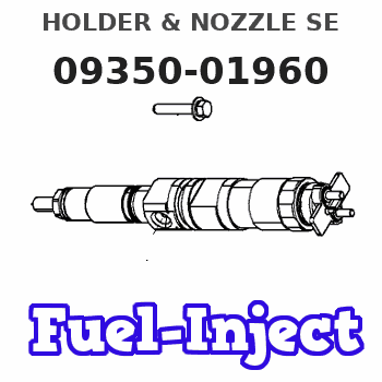
Information holder & nozzle se
Rating:
Components :
| 001. | HOLDER & NOZZLE SE | 09350-01960 |
Scheme ###:
| 000. | [01] | 09350-01960 | HOLDER & NOZZLE SE | 14941-53001 |
| 001. | [01] | 09310-01960 | HOLDER ASSY, NOZZL | 14941-53011 |
| 001-001. | [01] | 09311-11960 | BODY | 14941-53141 |
| 001-002. | [01] | 09312-10030 | PIN, NOZZLE HOLDER | 15108-53160 |
| 001-003. | [01] | 09312-70020 | SPRING, NOZZLE HOL | 15221-53171 |
| 001-004. | [01] | 09314-00080 | NIPPLE SUB-ASSY, O | 14117-42561 |
| 001-005. | [01] | 09315-10060 | CONNECTOR, NOZZLE | 14111-53031 |
| 001-006. | [01] | 09315-80010 | GASKET, INLET CONN | 14301-53381 |
| 001-007. | [01] | 09316-40242 | NUT, NOZZLE RETAIN | 14301-53281 |
| 001-008. | [01] | 09316-60010 | SCREW, HOLLOW | 14111-53411 |
| 001-009. | [01] | 09317-40011 | DISTANCE PIECE | 15221-53351 |
| 001-010. | [02] | 94901-81020 | WASHER, COPPER PLA | 15221-96661 |
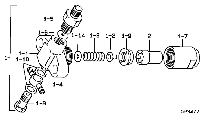
| 001-014. | [1C] | 09317-50200 | WASHER | 15221-98301 |
| 001-014. | [1C] | 09317-50120 | WASHER | 15221-98221 |
| 001-014. | [1C] | 09317-50130 | WASHER | 15221-98231 |
| 001-014. | [1C] | 09317-50140 | WASHER | 15221-98241 |
| 001-014. | [1C] | 09317-50150 | WASHER | 15221-98251 |
| 001-014. | [1C] | 09317-50160 | WASHER | 15221-98261 |
| 001-014. | [1C] | 09317-50170 | WASHER | 15221-98271 |
| 001-014. | [1C] | 09317-50180 | WASHER | 15221-98281 |
| 001-014. | [1C] | 09317-50190 | WASHER | 15221-98291 |
| 001-014. | [1C] | 09317-50110 | WASHER | 15221-98211 |
| 001-014. | [1C] | 09317-50100 | WASHER | 15221-98201 |
| 001-014. | [1C] | 09317-50010 | WASHER | 15021-53231 |
| 001-014. | [1C] | 09317-50020 | WASHER | 15221-98121 |
| 001-014. | [1C] | 09317-50030 | WASHER | 15221-98131 |
| 001-014. | [1C] | 09317-50040 | WASHER | 15221-98141 |
| 001-014. | [1C] | 09317-50050 | WASHER | 15221-98151 |
| 001-014. | [1C] | 09317-50060 | WASHER | 15221-98161 |
| 001-014. | [1C] | 09317-50070 | WASHER | 15221-98171 |
| 001-014. | [1C] | 09317-50080 | WASHER | 15221-98181 |
| 001-014. | [1C] | 09317-50090 | WASHER | 15221-98191 |
| 002. | [01] | 09340-00800 | NOZZLE ASSY | 14941-53611 |
Include in #3:
09350-01960
as HOLDER & NOZZLE SE
Include as Nozzle:
Cross reference number
| Part num | Firm num | Firm | Name |
| 09350-01960 | 14941-5300 | HOLDER & NOZZLE SE | |
| 14941-53001 | KUBOTA | HOLDER & NOZZLE SE |
Information:
1. Be sure O-ring seal (1) is in position on the fuel transfer pump. Put clean engine oil on the O-ring seal.2. Put fuel transfer pump (2) in position, and install the bolts that hold it in place.3. Remove the caps from the fuel line openings, and install fuel line (3).4. Prime the fuel system. See the Maintenance Guide for this procedure.Disassemble Fuel Transfer Pump
Start By:a. remove fuel transfer pump 1. Remove seal (1) from the fuel transfer pump.
Cover (2) is under spring tension. Remove the bolts that hold cover (2) slowly to prevent injury.
2. Remove bolts (3) and cover (2) from the housing. 3. Remove seals (4) and valve (5) from cover (2). 4. Remove spring (6) from the piston.
Mark the orientation of valve (8) as to its location in the housing.
5. Remove washer (7), valve (8) and the seal from the housing. 6. Remove piston (9) and sleeve (10) from the housing. 7. Remove seal (11) from sleeve (12). 8. Remove guide and tappet assembly (13) from the housing. 9. Remove seal (14) from guide (15).
If tappet (17) or the guide are damaged or worn, they must be replaced as a unit.
10. Remove ring (16) from tappet (17) and the tappet from guide (15). 11. Remove the bolts and cover (18) from the housing. 12. Remove seal (19) from cover (18). 13. Remove valve (20) from the housing if necessary. Assemble Fuel Transfer Pump
1. Install valve (2) in housing (1) as shown. 2. Put clean fuel on seal (4), and install it on cover (3).3. Install cover (3) on the housing.
The tappet and guide must be serviced as a unit.
4. Install tappet (6) in guide (5). Install ring (7) on tappet (6) to hold the tappet in the guide. 5. Put clean fuel on seal (8), and install it on guide and tappet assembly (9).6. Install guide and tappet assembly (9) in the housing as shown. 7. Put clean fuel on seal (10), and install it on sleeve (11).8. Install sleeve (11) in the housing. 9. Install piston (12) in the housing. 10. Install seal valve (14) and washer (13) in the housing as shown. Be sure valve (14) is the correct position in the housing. 11. Install spring (15) in the piston. 12. Install valve (18) in cover (16) as shown.13. Put clean fuel on seals (17), and put them in position on cover (16).14. Install cover (16) on the housing. 15. Put seal (19) in position on the fuel transfer pump.16. Install the fuel transfer pump on the fuel injection pump housing.End By:a. install fuel transfer pump