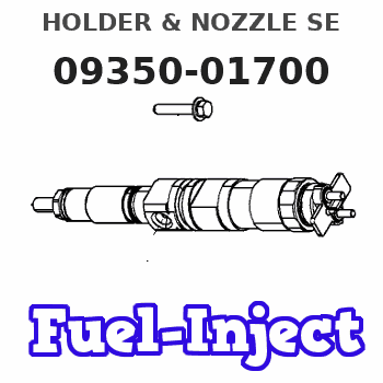
Information holder & nozzle se
Rating:
Components :
| 001. | HOLDER & NOZZLE SE | 09350-01700 |
Scheme ###:
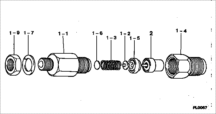
| 000. | [01] | 09350-01700 | HOLDER & NOZZLE SE | 30661-53020 |
| 001. | [01] | 09310-01700 | HOLDER ASSY, NOZZL | 30661-32300 |
| 001-001. | [01] | 09311-01700 | BODY SUB-ASSY, NOZ | 09311-01700 |
| 001-002. | [01] | 09312-10030 | PIN, NOZZLE HOLDER | 09312-10030 |
| 001-003. | [01] | 09312-70020 | SPRING, NOZZLE HOL | 09312-70020 |
| 001-004. | [01] | 09316-40420 | NUT, NOZZLE RETAIN | 09316-40420 |
| 001-005. | [01] | 09317-40011 | DISTANCE PIECE | 09317-40010 |
| 001-006. | [1C] | 09317-50120 | WASHER | 09317-50120 |
| 001-006. | [1C] | 09317-50130 | WASHER | 09317-50130 |
| 001-006. | [1C] | 09317-50140 | WASHER | 09317-50140 |
| 001-006. | [1C] | 09317-50150 | WASHER | 09317-50150 |
| 001-006. | [1C] | 09317-50160 | WASHER | 09317-50160 |
| 001-006. | [1C] | 09317-50170 | WASHER | 09317-50170 |
| 001-006. | [1C] | 09317-50180 | WASHER | 09317-50180 |
| 001-006. | [1C] | 09317-50190 | WASHER | 09317-50190 |
| 001-006. | [1C] | 09317-50200 | WASHER | 09317-50200 |
| 001-006. | [1C] | 09317-50110 | WASHER | 09317-50110 |
| 001-006. | [1C] | 09317-50100 | WASHER | 09317-50100 |
| 001-006. | [1C] | 09317-50010 | WASHER | 09317-50010 |
| 001-006. | [1C] | 09317-50020 | WASHER | 09317-50020 |
| 001-006. | [1C] | 09317-50030 | WASHER | 09317-50030 |
| 001-006. | [1C] | 09317-50040 | WASHER | 09317-50040 |
| 001-006. | [1C] | 09317-50050 | WASHER | 09317-50050 |
| 001-006. | [1C] | 09317-50060 | WASHER | 09317-50060 |
| 001-006. | [1C] | 09317-50070 | WASHER | 09317-50070 |
| 001-006. | [1C] | 09317-50080 | WASHER | 09317-50080 |
| 001-006. | [1C] | 09317-50090 | WASHER | 09317-50090 |
| 001-007. | [01] | 09324-50110 | WASHER | 09324-50110 |
| 001-009. | [01] | 94905-02500 | NUT, HEXAGON | 94905-02500 |
| 001-009. | [01] | 94905-02480 | NUT, HEXAGON | |
| 002. | [01] | 09340-00060 | NOZZLE ASSY | MM100118 |
Include in #3:
09350-01700
as HOLDER & NOZZLE SE
Include as Nozzle:
1900000020
as Nozzle
Cross reference number
| Part num | Firm num | Firm | Name |
| 09350-01700 | 30661-5302 | HOLDER & NOZZLE SE | |
| 30661-53020 | MITSUBISHI | HOLDER & NOZZLE SE |
Information:
Recommended Procedure Without Chassis Dynamometer
Possible Causes/Corrections Minor Operating FaultsTo help identify a problem before a more involved troubleshooting procedure is started, follow the procedure given in the "Primary Engine Checks" section. Fuel Ratio Control Out Of Adjustment Or DefectiveFollow the procedure in the Testing and Adjusting Section of this Service Manual. Fuel Injection Timing Not CorrectFollow the procedures in the Testing and Adjusting Section of this Service Manual. Check Engine PerformanceInstall the tooling and follow the procedure given in the "Road Test" section. Fuel Settings Not CorrectIf the Road Test indicates a problem, the governor fuel settings should be verified. See the Testing and Adjusting Section of this Service Manual for the necessary procedures. Also, refer back to the information learned earlier (see "Owner Operator Input" section) about the truck specifications and application and judge whether or not the engine is performing as expected or customer expectation is realistic. Any Further Diagnosis Must Be Done On A Chassis DynamometerIf the fuel settings are correct and the above procedures have been followed without finding the problem a Power Analysis Report (PAR), Level II, must be done on the engine. See Special Instruction, Form Nos. SEHS8025 and SEHS7886 for the correct tools and procedures to use.
Possible Causes/Corrections Minor Operating FaultsTo help identify a problem before a more involved troubleshooting procedure is started, follow the procedure given in the "Primary Engine Checks" section. Fuel Ratio Control Out Of Adjustment Or DefectiveFollow the procedure in the Testing and Adjusting Section of this Service Manual. Fuel Injection Timing Not CorrectFollow the procedures in the Testing and Adjusting Section of this Service Manual. Check Engine PerformanceInstall the tooling and follow the procedure given in the "Road Test" section. Fuel Settings Not CorrectIf the Road Test indicates a problem, the governor fuel settings should be verified. See the Testing and Adjusting Section of this Service Manual for the necessary procedures. Also, refer back to the information learned earlier (see "Owner Operator Input" section) about the truck specifications and application and judge whether or not the engine is performing as expected or customer expectation is realistic. Any Further Diagnosis Must Be Done On A Chassis DynamometerIf the fuel settings are correct and the above procedures have been followed without finding the problem a Power Analysis Report (PAR), Level II, must be done on the engine. See Special Instruction, Form Nos. SEHS8025 and SEHS7886 for the correct tools and procedures to use.