Information holder & nozzle se
Rating:
Components :
| 001. | HOLDER & NOZZLE SE | 09350-01690 |
Scheme ###:
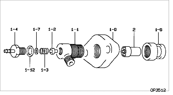
| 000. | [01] | 09350-01690 | HOLDER & NOZZLE SE | MM105106 |
| 001. | [01] | 09310-01690 | HOLDER ASSY, NOZZL | MM105107 |
| 001-001. | [01] | 09311-01690 | BODY SUB-ASSY, NOZ | MM514454 |
| 001-002. | [01] | 09312-10030 | PIN, NOZZLE HOLDER | MM500135 |
| 001-003. | [01] | 09312-70020 | SPRING, NOZZLE HOL | ME022313 |
| 001-004. | [01] | 09314-00071 | NIPPLE SUB-ASSY, O | MM500279 |
| 001-006. | [01] | 09316-40651 | NUT, NOZZLE RETAIN | MM500217 |
| 001-007. | [1C] | 09317-50300 | WASHER | MM500794 |
| 001-007. | [1C] | 09317-50610 | WASHER | MM500795 |
| 001-007. | [1C] | 09317-50620 | WASHER | MM500796 |
| 001-007. | [1C] | 09317-50630 | WASHER | MM500797 |
| 001-007. | [1C] | 09317-50640 | WASHER | MM500798 |
| 001-007. | [1C] | 09317-50650 | WASHER | MM500799 |
| 001-007. | [1C] | 09317-50290 | WASHER | MM500793 |
| 001-007. | [1C] | 09317-50280 | WASHER | MM500792 |
| 001-007. | [1C] | 09317-50270 | WASHER | MM500791 |
| 001-007. | [1C] | 09317-50210 | WASHER | MM500785 |
| 001-007. | [1C] | 09317-50220 | WASHER | MM500786 |
| 001-007. | [1C] | 09317-50230 | WASHER | MM500787 |
| 001-007. | [1C] | 09317-50240 | WASHER | P820-8634 |
| 001-007. | [1C] | 09317-50250 | WASHER | P820-8635 |
| 001-007. | [1C] | 09317-50260 | WASHER | MM500790 |
| 001-008. | [01] | 09326-60030 | FLANGE | MM500218 |
| 001-012. | [01] | 94901-80350 | WASHER, COPPER PLA | ME702922 |
| 002. | [01] | 09340-00620 | NOZZLE ASSY | 30896-69701 |
Include in #3:
09350-01690
as HOLDER & NOZZLE SE
Include as Nozzle:
Cross reference number
| Part num | Firm num | Firm | Name |
| 09350-01690 | MM105106 | HOLDER & NOZZLE SE | |
| MM105106 | MITSUBISHI | HOLDER & NOZZLE SE |
Information:
Fuel System Inspection
A problem with the components that send fuel to the engine can cause low fuel pressure. This can decrease engine performance.
Fuel System
(1) Tube assembly (return to tank from fuel passage in cylinder head). (2) Fuel outlet port (to tank). (3) Tube assembly (from transfer pump to fuel filter base). (4) Tube assembly (from fuel filter base to fuel passage in cylinder head). (5) Fuel inlet port (to fuel transfer pump). (6) Screen. (7) Fuel filter.1. Check the fuel level in the fuel tank. Look at the cap for the fuel tank to make sure the vent is not filled with dirt.2. Check the fuel lines for or air fuel leakage. Be sure the fuel supply line does not have a restriction or a bad bend.3. Install a new secondary fuel filter. Clean screen (6) located in the inlet fitting of the fuel transfer pump.4. Inspect the orifice in tube assembly (1) to see that there is no restriction for proper operation.Checking Engine Cylinders Separately
Temperature of an exhaust manifold port, when the engine runs at low idle speed, can be an indication of the condition of a fuel injector. Low temperature at an exhaust manifold port is an indication of no fuel to the cylinder. This can possibly be an indication of an inoperative injector. Extra high temperature at an exhaust manifold port can be an indication of too much fuel to the cylinder, caused by a malfunctioning injector. The difference between cylinders should be no more than 70°C (158°F).With the valve cover removed and the engine idling, the control shaft levers allow each injector to be actuated individually to the "FUEL ON" position for a few seconds. This causes excess fuel to be injected into that particular cylinder, causing a loud combustion "knock". If actuating an injector in this fashion briefly does not result in a loud combustion "knock", there may be a problem with the injector, the fuel supply to the injector, or the seal between the injector and the brass sleeve.Use the 1U8865 Infrared Thermometer to check exhaust temperature. The Operator's Manual, Form No. NEHS0510, for the 1U8865 Infrared Thermometer gives complete operating and maintenance instructions for this tool.Start Up Procedure
Use this procedure when an engine is started for the first time after work is done on the fuel system or governor.1. Disconnect the air inlet system from the turbocharger.2. Have a person in position near the turbocharger air inlet with a piece of steel plate large enough to completely cover the turbocharger air inlet.
Be careful when plate is put against air inlet opening. Due to excessive suction, the plate can be pulled quickly against air inlet opening. To avoid crushed fingers, do not put fingers between plate and air inlet opening.
3. Start the engine. If the engine starts to run too fast or runs out of control, immediately put the steel plate against the turbocharger air inlet. This will stop the air supply to the engine, and the engine will stop.Governor
The only "ON-ENGINE"