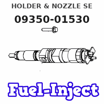
Information holder & nozzle se
Rating:
Components :
| 001. | HOLDER & NOZZLE SE | 09350-01530 |
Scheme ###:
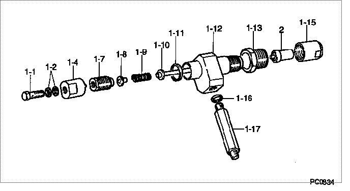
| 000. | [01] | 09350-01530 | HOLDER & NOZZLE SE | 61141-13100 |
| 001. | [01] | 09310-01530 | HOLDER ASSY, NOZZL | 61141-13110 |
| 001-001. | [01] | 09316-60010 | SCREW, HOLLOW | 09316-60010 |
| 001-002. | [02] | 94901-81020 | WASHER, COPPER PLA | 94901-81020 |
| 001-004. | [01] | 09313-40191 | NUT, CAP | 09313-40190 |
| 001-007. | [01] | 09312-90150 | SCREW, CAP | 09312-90150 |
| 001-008. | [01] | 09312-80090 | SEAT, SPRING | 09312-80090 |
| 001-009. | [01] | 09312-70260 | SPRING, NOZZLE HOL | 09312-70260 |
| 001-010. | [01] | 09312-00041 | PIN SUB-ASSY, PRES | 09312-00040 |
| 001-011. | [01] | 09313-30100 | GASKET | 09313-30100 |
| 001-012. | [01] | 09311-11530 | BODY | 09311-11530 |
| 001-013. | [01] | 09316-20041 | SCREW, CYLINDER | 09316-20041 |
| 001-015. | [01] | 09316-40320 | NUT, NOZZLE RETAIN | 09316-40320 |
| 001-016. | [01] | 09315-80010 | GASKET, INLET CONN | 09315-80010 |
| 001-017. | [01] | 09315-00100 | CONNECTOR SUB-ASSY | 09315-00100 |
| 002. | [01] | 09340-00690 | NOZZLE ASSY | 61141-13120 |
Include in #3:
09350-01530
as HOLDER & NOZZLE SE
Include as Nozzle:
Cross reference number
| Part num | Firm num | Firm | Name |
| 09350-01530 | 61141-1310 | HOLDER & NOZZLE SE | |
| 61141-13100 | KOMATSU | HOLDER & NOZZLE SE |
Information:
Possible Causes/Corrections
Dirty Air Cleaner/If the air cleaner has a restriction indicator, see if the red piston is in view. If there is no restriction indicator, restriction can be checked with a water manometer or a vacuum gauge (which measures in inches of water). Make a connection to the piping between the air cleaner and the inlet of the turbocharger. Check with the engine running at full load rpm. Maximum restriction is 635 mm (25 in.) of water. If a gauge is not available, visually check the air cleaner element for dirt. If the element is dirty, clean the element or install a new element. Air Inlet Piping Damage or Restriction/Make a visual inspection of the air inlet system and check for damage to piping, rags in the inlet piping, or damage to the rain cap or the cap pushed too far on the inlet pipe. If no damage is seen, check inlet restriction with a clean air cleaner element. Exhaust System Restriction/Make a visual inspection of the exhaust system. Check for damage to piping or for a bad muffler. If no damage is found, you can check the system by checking the back pressure from the exhaust (pressure difference measurement between exhaust outlet and atmosphere). The back pressure must not be more than 1016 mm (40 in.) of water. You can also check by removing the exhaust pipes from the exhaust manifolds. With the exhaust pipes removed, start and load the engine on a chassis dynamometer to see if the problem is corrected. Fuel Injection Timing Not Correct/Check and make necessary adjustments as in Testing and Adjusting section of this Service Manual. Fuel Setting Is Not Correct/Check and make necessary adjustments as in Testing and Adjusting Section of this Service Manual. See the FUEL SETTING AND RELATED INFORMATION FICHE for the correct fuel setting. Low Quality Fuel/Test the engine with fuel according to recommendations by Caterpillar Tractor Co. For more information see Special Instruction, Form No. SEHS7067, Fuel Recommendations For Caterpillar Diesel Engines. Also, Special Instruction, Form No. SEHS6947 has fuel correction factors and tables. Bad Fuel Nozzle(s)/Bad fuel nozzles will normally cause the engine to misfire and run rough, but can cause too much smoke with engine still running smooth. Remove the fuel nozzles and test as in Testing and Adjusting section of this Service Manual. Valve Adjustment Not Correct or Valve Leakage/Check and make necessary adjustments as in Testing and Adjusting section of this Service Manual. Intake valve clearance is 0.38 mm (.015 in.) and exhaust valve clearance is 0.64 mm (.025 in.). Valve leakage normally causes the engine to misfire and run rough. Bad Fuel Injection Pump/An injection pump can have a good fuel flow coming from it but cause rough running because of slow timing that is caused by wear on the bottom end of the plunger. See the Testing and Adjusting section in this Service Manual for the correct specifications and procedure to check the plungers and lifters.Fuel pumps which are severely scored
Dirty Air Cleaner/If the air cleaner has a restriction indicator, see if the red piston is in view. If there is no restriction indicator, restriction can be checked with a water manometer or a vacuum gauge (which measures in inches of water). Make a connection to the piping between the air cleaner and the inlet of the turbocharger. Check with the engine running at full load rpm. Maximum restriction is 635 mm (25 in.) of water. If a gauge is not available, visually check the air cleaner element for dirt. If the element is dirty, clean the element or install a new element. Air Inlet Piping Damage or Restriction/Make a visual inspection of the air inlet system and check for damage to piping, rags in the inlet piping, or damage to the rain cap or the cap pushed too far on the inlet pipe. If no damage is seen, check inlet restriction with a clean air cleaner element. Exhaust System Restriction/Make a visual inspection of the exhaust system. Check for damage to piping or for a bad muffler. If no damage is found, you can check the system by checking the back pressure from the exhaust (pressure difference measurement between exhaust outlet and atmosphere). The back pressure must not be more than 1016 mm (40 in.) of water. You can also check by removing the exhaust pipes from the exhaust manifolds. With the exhaust pipes removed, start and load the engine on a chassis dynamometer to see if the problem is corrected. Fuel Injection Timing Not Correct/Check and make necessary adjustments as in Testing and Adjusting section of this Service Manual. Fuel Setting Is Not Correct/Check and make necessary adjustments as in Testing and Adjusting Section of this Service Manual. See the FUEL SETTING AND RELATED INFORMATION FICHE for the correct fuel setting. Low Quality Fuel/Test the engine with fuel according to recommendations by Caterpillar Tractor Co. For more information see Special Instruction, Form No. SEHS7067, Fuel Recommendations For Caterpillar Diesel Engines. Also, Special Instruction, Form No. SEHS6947 has fuel correction factors and tables. Bad Fuel Nozzle(s)/Bad fuel nozzles will normally cause the engine to misfire and run rough, but can cause too much smoke with engine still running smooth. Remove the fuel nozzles and test as in Testing and Adjusting section of this Service Manual. Valve Adjustment Not Correct or Valve Leakage/Check and make necessary adjustments as in Testing and Adjusting section of this Service Manual. Intake valve clearance is 0.38 mm (.015 in.) and exhaust valve clearance is 0.64 mm (.025 in.). Valve leakage normally causes the engine to misfire and run rough. Bad Fuel Injection Pump/An injection pump can have a good fuel flow coming from it but cause rough running because of slow timing that is caused by wear on the bottom end of the plunger. See the Testing and Adjusting section in this Service Manual for the correct specifications and procedure to check the plungers and lifters.Fuel pumps which are severely scored