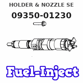
Information holder & nozzle se
Rating:
Components :
| 001. | HOLDER & NOZZLE SE | 09350-01230 |
Scheme ###:
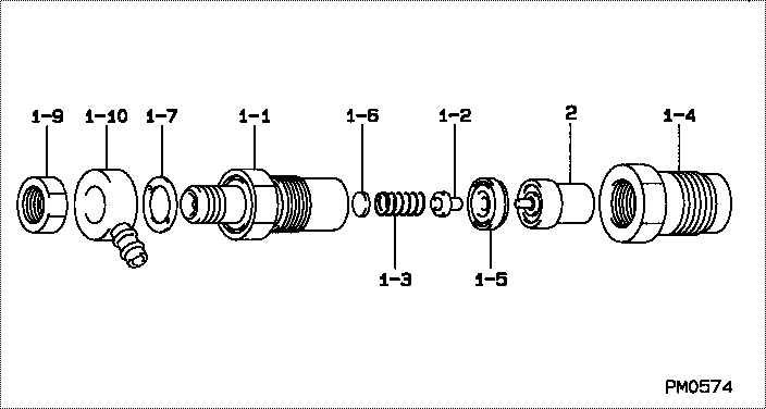
| 000. | [01] | 09350-01230 | HOLDER & NOZZLE SE | 15221-53001 |
| 001. | [01] | 09310-01230 | HOLDER ASSY, NOZZL | |
| 001-001. | [01] | 09311-00490 | BODY SUB-ASSY, NOZ | |
| 001-002. | [01] | 09312-10030 | PIN, NOZZLE HOLDER | 15108-53160 |
| 001-003. | [01] | 09312-70020 | SPRING, NOZZLE HOL | 15221-53171 |
| 001-004. | [01] | 09316-41201 | NUT, NOZZLE RETAIN | |
| 001-005. | [01] | 09317-40011 | DISTANCE PIECE | 15221-53351 |
| 001-006. | [1C] | 09317-50120 | WASHER | 15221-98221 |
| 001-006. | [1C] | 09317-50130 | WASHER | 15221-98231 |
| 001-006. | [1C] | 09317-50140 | WASHER | 15221-98241 |
| 001-006. | [1C] | 09317-50150 | WASHER | 15221-98251 |
| 001-006. | [1C] | 09317-50160 | WASHER | 15221-98261 |
| 001-006. | [1C] | 09317-50170 | WASHER | 15221-98271 |
| 001-006. | [1C] | 09317-50180 | WASHER | 15221-98281 |
| 001-006. | [1C] | 09317-50190 | WASHER | 15221-98291 |
| 001-006. | [1C] | 09317-50200 | WASHER | 15221-98301 |
| 001-006. | [1C] | 09317-50110 | WASHER | 15221-98211 |
| 001-006. | [1C] | 09317-50100 | WASHER | 15221-98201 |
| 001-006. | [1C] | 09317-50010 | WASHER | 15021-53231 |
| 001-006. | [1C] | 09317-50020 | WASHER | 15221-98121 |
| 001-006. | [1C] | 09317-50030 | WASHER | 15221-98131 |
| 001-006. | [1C] | 09317-50040 | WASHER | 15221-98141 |
| 001-006. | [1C] | 09317-50050 | WASHER | 15221-98151 |
| 001-006. | [1C] | 09317-50060 | WASHER | 15221-98161 |
| 001-006. | [1C] | 09317-50070 | WASHER | 15221-98171 |
| 001-006. | [1C] | 09317-50080 | WASHER | 15221-98181 |
| 001-006. | [1C] | 09317-50090 | WASHER | 15221-98191 |
| 001-007. | [01] | 09324-50040 | WASHER | 15221-94021 |
| 001-009. | [01] | 94905-02480 | NUT, HEXAGON | 15221-92021 |
| 001-010. | [01] | 09317-00140 | RING SUB-ASSY, PAC | 15221-95681 |
| 002. | [01] | 09340-00100 | NOZZLE ASSY | 15021-53611 |
Include in #3:
09350-01230
as HOLDER & NOZZLE SE
Include as Nozzle:
Cross reference number
| Part num | Firm num | Firm | Name |
| 09350-01230 | 15221-5300 | HOLDER & NOZZLE SE | |
| 15221-53001 | KUBOTA | HOLDER & NOZZLE SE |
Information:
1. Disconnect fuel line (1) from the fuel transfer pump. Disconnect fuel line (2) from the fuel injection pump housing. Remove line (3) from the fuel ratio control and aftercooler housing. 2. Disconnect fuel injection lines (4) from the fuel injection pump housing.
Do not disconnect the air line from the air compressor governor until the air pressure is zero.
3. Loosen the bleed valves, and release the air pressure in the air tank. 4. Remove air line (5). Remove coolant line (6). 5. The weight of the fuel injection pump housing and governor is 57 kg (125 lb.). Attach a hoist to the fuel injection pump housing, and remove bolts (7). 6. Remove the two nuts and two bolts (8) and bolt (9). Remove fuel injection pump housing and governor (10). 7. Remove O-ring seals (11) from the fuel injection pump housing.Install Fuel Injection Pump Housing And Governor
1. Attach a hoist to the fuel injection pump housing and governor (1). Be sure that the three O-ring seals are in position in the fuel injection pump housing. Install the fuel injection pump housing and governor on the timing gear housing. 2. Connect air line (2) and water line (3) to the air compressor. 3. Connect fuel injection lines (4) to fuel injection pump housing, and tighten the fuel injection line nuts to a torque of 40 7 N m (30 5 lb.ft.) with tool (C). 4. Connect fuel line (5) to fuel injection pump housing, and connect fuel line (6) to the fuel transfer pump. Install line (7) between the fuel ratio control and aftercooler housing. For timing of the fuel injection pump, see Install Automatic Timing Advance.END BY:a. install automatic timing advance