Information holder & nozzle se
Rating:
Components :
| 001. | HOLDER & NOZZLE SE | 09350-01200 |
Scheme ###:
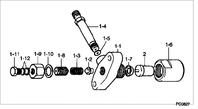
| 000. | [01] | 09350-01200 | HOLDER & NOZZLE SE | EZ01642 |
| 001. | [01] | 09310-01200 | HOLDER ASSY, NOZZL | |
| 001-001. | [01] | 09311-10551 | BODY | |
| 001-002. | [01] | 09312-10030 | PIN, NOZZLE HOLDER | 09312-10030 |
| 001-003. | [01] | 09312-70020 | SPRING, NOZZLE HOL | 09312-70020 |
| 001-004. | [01] | 09315-00130 | CONNECTOR SUB-ASSY | EZ0087404 |
| 001-005. | [01] | 09315-80010 | GASKET, INLET CONN | EZ0087405 |
| 001-006. | [01] | 09316-40600 | NUT, NOZZLE RETAIN | EZ0164206 |
| 001-007. | [01] | 09317-40011 | DISTANCE PIECE | EZ0087407 |
| 001-008. | [01] | 09313-10130 | SCREW, ADJUST | EZ0087408 |
| 001-009. | [01] | 09313-40150 | NUT, CAP | 09313-40150 |
| 001-010. | [01] | 09324-50052 | WASHER | ME022312 |
| 001-011. | [01] | 94918-00152 | SCREW, HOLLOW | 00918-00152 |
| 001-012. | [02] | 94901-81020 | WASHER, COPPER PLA | 94901-81020 |
| 002. | [01] | 09340-00340 | NOZZLE ASSY | MM300151 |
Include in #3:
09350-01200
as HOLDER & NOZZLE SE
Include as Nozzle:
Cross reference number
| Part num | Firm num | Firm | Name |
| 09350-01200 | EZ01642 | HOLDER & NOZZLE SE | |
| EZ01642 | MITSUBISHI | HOLDER & NOZZLE SE |
Information:
1. Remove the two bolts, and remove the fuel ratio control from the governor. Remove O-ring seal (1) from the fuel ratio control. 2. Put tooling (A) in a vise as shown so that the station being used is not over the vise jaw. Place the fuel ratio control over the pins in tooling (A). Remove cover (2) and the gasket from fuel ratio control.
There is spring force behind cover (3). Hold cover (3) in position, and slowly remove the bolts that hold it to release the spring force.
3. Remove cover (3) from housing (4). 4. Remove nut (5) and stop (6) from the cover. 5. Remove spring (9), washer (7), and diaphragm (10) from retainer (8). Remove retainer (8) from housing (11). 6. Remove nut (16) from extension (15), and remove the extension from retainer (8). Remove valve (12), spring (13) and O-ring seal (14) from the extension. 7. Remove spring (18), retainer (17) and spring (19) from the housing. 8. Remove piston assembly (20) from the housing. 9. Use tooling (B), and remove snap ring (21) and the wave washers from valve assembly (22). Remove piston assembly (23) from the valve assembly.10. Remove seal (24) from piston (23). 11. If necessary, remove stem (26) from valve (25).12. Clean and inspect all parts. Make a replacement of all parts that are worn or damaged.Assemble Fuel Ratio Control
1. Assemble stem (2) to valve (1) using 9S3265 Retaining Compound. 2. Put seal (4) on piston (3), and put piston (3) on valve assembly (5). 3. Put two wave washers in position on valve (5), and use tooling (A) to install the snap ring on the valve assembly. 4. Place housing (7) on tooling (B), and put tooling (C) into the bore of the housing. Lubricate tooling (C) with clean engine oil.5. Put a small amount of clean oil on the seal of the piston assembly, and push piston assembly (6) into position with a smooth swift motion. 6. Place spring (8) and retainer and spring (9) in position in housing (7). 7. Put O-ring seal (12) on extension (13). Put spring (11) and valve (10) in position on the extension.8. Lubricate O-ring seal (12) with clean engine oil. Install extension (13) in retainer (14). Install nut (15). 9. Put diaphragm (18), washer (17) and spring (16) in position on retainer (14). Install retainer (14) in housing (7). 10. Install stop (20) and nut (19) in the cover. 11. Hold retainer (14) in position, and install cover (21) on the housing. Install the bolts that hold the cover, and tighten them to a torque of 9 3 N m (7 2 lb.ft.). 12. Make a replacement of the gasket for cover (22), and install the cover. 13. Put O-ring seal (23) in position on the fuel ratio control.14. Put the fuel ratio control in position on the governor. Make sure the flange on the end of the fuel ratio control is behind the groove (slot) in the