Information holder & nozzle se
Rating:
Components :
| 001. | HOLDER & NOZZLE SE | 09350-01011 |
Scheme ###:
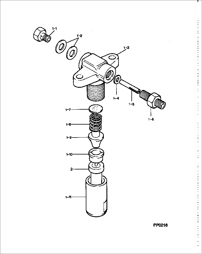
| 000. | [01] | 09350-01011 | HOLDER & NOZZLE SE | 14412-53001 |
| 001. | [01] | 09310-01011 | HOLDER ASSY, NOZZL | |
| 001-001. | [01] | 09316-60010 | SCREW, HOLLOW | 14111-53411 |
| 001-002. | [02] | 94901-81020 | WASHER, COPPER PLA | 15221-96661 |
| 001-003. | [01] | 09311-10580 | BODY | |
| 001-004. | [01] | 09315-80010 | GASKET, INLET CONN | 14301-53381 |
| 001-005. | [01] | 09315-20010 | FILTER, BAR | |
| 001-006. | [01] | 09315-10060 | CONNECTOR, NOZZLE | 14111-53031 |
| 001-007. | [1C] | 09317-50120 | WASHER | 15221-98221 |
| 001-007. | [1C] | 09317-50130 | WASHER | 15221-98231 |
| 001-007. | [1C] | 09317-50140 | WASHER | 15221-98241 |
| 001-007. | [1C] | 09317-50150 | WASHER | 15221-98251 |
| 001-007. | [1C] | 09317-50160 | WASHER | 15221-98261 |
| 001-007. | [1C] | 09317-50170 | WASHER | 15221-98271 |
| 001-007. | [1C] | 09317-50180 | WASHER | 15221-98281 |
| 001-007. | [1C] | 09317-50190 | WASHER | 15221-98291 |
| 001-007. | [1C] | 09317-50200 | WASHER | 15221-98301 |
| 001-007. | [1C] | 09317-50110 | WASHER | 15221-98211 |
| 001-007. | [1C] | 09317-50100 | WASHER | 15221-98201 |
| 001-007. | [1C] | 09317-50010 | WASHER | 15021-53231 |
| 001-007. | [1C] | 09317-50020 | WASHER | 15221-98121 |
| 001-007. | [1C] | 09317-50030 | WASHER | 15221-98131 |
| 001-007. | [1C] | 09317-50040 | WASHER | 15221-98141 |
| 001-007. | [1C] | 09317-50050 | WASHER | 15221-98151 |
| 001-007. | [1C] | 09317-50060 | WASHER | 15221-98161 |
| 001-007. | [1C] | 09317-50070 | WASHER | 15221-98171 |
| 001-007. | [1C] | 09317-50080 | WASHER | 15221-98181 |
| 001-007. | [1C] | 09317-50090 | WASHER | 15221-98191 |
| 001-008. | [01] | 09312-70020 | SPRING, NOZZLE HOL | 15221-53171 |
| 001-009. | [01] | 09312-10030 | PIN, NOZZLE HOLDER | 15108-53160 |
| 001-010. | [01] | 09317-40011 | DISTANCE PIECE | 15221-53351 |
| 001-011. | [01] | 09316-40242 | NUT, NOZZLE RETAIN | 14301-53281 |
| 002. | [01] | 09340-00330 | NOZZLE ASSY | 14301-53612 |
Include in #3:
09350-01011
as HOLDER & NOZZLE SE
Cross reference number
| Part num | Firm num | Firm | Name |
| 09350-01011 | 14412-5300 | HOLDER & NOZZLE SE |
Information:
2. Turn the crankshaft until two pistons are at bottom center.3. Remove connecting rod caps (1) from the two connecting rods. Put pieces of rubber hose or tape on the threads of the connecting rod bolts as protection for the crankshaft. 4. Push the pistons and connecting rods away from the crankshaft until the piston rings are above the cylinder block.5. Remove the two pistons (2) and the connecting rods. Keep each connecting rod cap with its respective connecting rod and piston. Put identification on each connecting rod as to its location for use at installation.
Do not turn the crankshaft while any of the connecting rods are in the engine without the caps installed.
6. Do Steps 2 through 5 for the remainder of the pistons.Install Pistons
Two different pistons are used in 3208 Truck Engines. One piston has a crater volume of 50.4 1.3 cm3 (3.08 .07 in.3), and the other piston has a crater volume of 58.8 1.2 cm3 (3.59 .07 in.3). Check the part number stamped on the top of the piston and refer to the parts book to be sure the correct replacement piston is used. The correct piston must be installed in the engine. If the wrong piston is installed, much damage to the engine will be the result.
1. Put clean engine oil on the piston rings, connecting rod bearings, cylinder walls and crankshaft bearing journals.2. Turn the crankshaft until the bearing journal for the pistons to be installed is at bottom center.3. Make sure the piston ring gaps are at least 120° apart on the piston. 4. Use tool (A) and install the piston in position in the same cylinder bore from which it was removed. The hole (crater) in the top of the piston must be toward (nearest) the center of the engine. For more detail about the installation of connecting rod bearings, see REMOVE AND INSTALL CONNECTING ROD BEARINGS.5. Check the bearing clearances with tool (B).6. Put 2P2506 Thread Lubricant on the threads of the bolts and contact surfaces of the nuts for the connecting rod caps.
When the connecting rod caps are installed, make sure that the number on the side of the cap is next to and respective with the number on the side of the connecting rod.
7. Put the cap (1) in position on the connecting rod and install the nuts. Tighten the nuts to a torque of 40 4 N m (30 3 lb.ft.). Put a mark on each nut and the end of each bolt. Tighten the nuts 60 5° more. 8. Check the side clearance between two connecting rods on the same crankshaft journal. Clearance must be 0.08 to 0.84 mm (.003 to .033 in.) for new rods.9. Do Steps 1 through 8 for the remainder of the pistons.end by:a) install cylinder headsb) install oil panDisassemble Pistons
start by:a) remove pistons1. Remove the rings from the piston with tool (A). 2. Remove the bearings from the connecting rod and connecting rod