Information holder & nozzle se
Rating:
Components :
| 001. | HOLDER & NOZZLE SE | 09350-00990 |
Scheme ###:
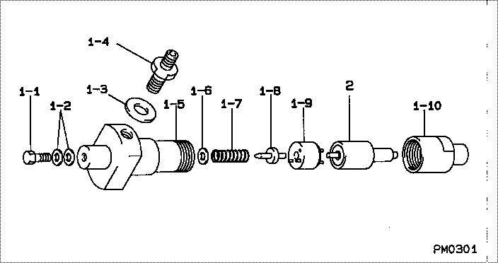
| 000. | [01] | 09350-00990 | HOLDER & NOZZLE SE | 01900371 |
| 001. | [01] | 09310-00990 | HOLDER ASSY, NOZZL | 0931000990 |
| 001-001. | [01] | 94918-00152 | SCREW, HOLLOW | |
| 001-002. | [02] | 94901-81020 | WASHER, COPPER PLA | 21706370 |
| 001-003. | [01] | 09315-80010 | GASKET, INLET CONN | |
| 001-004. | [01] | 09315-00110 | CONNECTOR SUB-ASSY | 01900291 |
| 001-005. | [01] | 09311-00270 | BODY SUB-ASSY, NOZ | 0931100270 |
| 001-006. | [1C] | 09317-50300 | WASHER | 0931750300 |
| 001-006. | [1C] | 09317-50610 | WASHER | 21900280 |
| 001-006. | [1C] | 09317-50620 | WASHER | 21900290 |
| 001-006. | [1C] | 09317-50630 | WASHER | 21900300 |
| 001-006. | [1C] | 09317-50640 | WASHER | 21900310 |
| 001-006. | [1C] | 09317-50650 | WASHER | 21900480 |
| 001-006. | [1C] | 09317-50290 | WASHER | 0931750290 |
| 001-006. | [1C] | 09317-50280 | WASHER | 0931750280 |
| 001-006. | [1C] | 09317-50270 | WASHER | 21900450 |
| 001-006. | [1C] | 09317-50210 | WASHER | 21900250 |
| 001-006. | [1C] | 09317-50220 | WASHER | 21900260 |
| 001-006. | [1C] | 09317-50230 | WASHER | 21900410 |
| 001-006. | [1C] | 09317-50240 | WASHER | 21900420 |
| 001-006. | [1C] | 09317-50250 | WASHER | 21900430 |
| 001-006. | [1C] | 09317-50260 | WASHER | |
| 001-007. | [01] | 09312-70120 | SPRING, NOZZLE HOL | 21900320 |
| 001-008. | [01] | 09312-10030 | PIN, NOZZLE HOLDER | 0931210030 |
| 001-009. | [01] | 09322-00010 | PACKING SUB-ASSY, | 21900340 |
| 001-010. | [01] | 09316-40430 | NUT, NOZZLE RETAIN | 21900360 |
| 002. | [01] | 09340-00450 | NOZZLE ASSY | 01900401 |
Include in #3:
09350-00990
as HOLDER & NOZZLE SE
Include as Nozzle:
Cross reference number
| Part num | Firm num | Firm | Name |
| 09350-00990 | 01900371 | HOLDER & NOZZLE SE | |
| 01900371 | MITSUI DEUTZ | HOLDER & NOZZLE SE |
Information:
1. Put gasket (2) in position. Make an alignment with the lever in the shutoff housing with the plunger in the fuel ratio control. control.2. Install fuel ratio control (1) and the bolts that hold it.Disassemble Fuel Ratio Control
start by:a) remove fuel ratio control1. Remove solenoid (1) from the fuel ratio control. 2. Remove bolts (3) and covers (2) and (4). Remove diaphragm (11) and piston (17). Remove gasket (16) from cover (4).
Spring force is present. Slowly loosen the two bolts to release the force.
3. Remove two bolts (5), cover (6) and spring (15).
Spring force is present. Hold diaphragm assembly in position and remove pin (14).
4. Remove pin (14) and slowly release the spring force.5. Remove spring (8) and bolt (7) from housing (12).6. Remove washer (10) and diaphragm (9) from retainer (13).Assemble Fuel Ratio Control
1. Assemble washer (3), diaphragm (2) and retainer (1).2. Install bolt (4) in housing (10).3. Install spring (5), diaphragm assembly (11) and pin (6) in housing (10).4. Install spring (22) in cover (7). Install cover (7) on housing (10) with the two bolts (16) that hold it. 5. Install gasket (13) on cover (8). Install piston (14) to cover (8). Install diaphragm (15) in cover (9). 6. Put covers (8) and (9) in position on cover (7) with the bolts that hold them.7. Install solenoid (17) on the fuel ratio control. end by:a) install fuel ratio control For adjustment of fuel ratio control, see TESTING AND ADJUSTING.
Have questions with 09350-00990?
01900371
HOLDER & NOZZLE SE
01900590KZ
HOLDER ASSY, NOZZL
01900610KZ
HOLDER & NOZZLE SE
04009-03160
04230-30120