Information holder & nozzle se
Rating:
Components :
| 001. | HOLDER & NOZZLE SE | 09350-00771 |
Scheme ###:
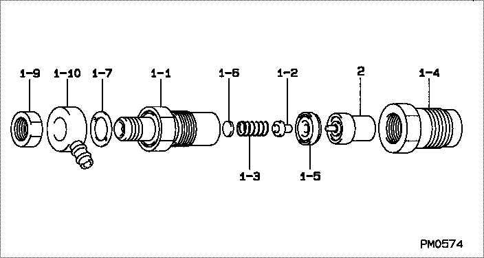
| 000. | [01] | 09350-00771 | HOLDER & NOZZLE SE | P820-80041 |
| 001. | [01] | 09310-00771 | HOLDER ASSY, NOZZL | P818-0022 |
| 001-001. | [01] | 09311-00253 | BODY SUB-ASSY, NOZ | P812-83052 |
| 001-002. | [01] | 09312-10250 | PIN, NOZZLE HOLDER | MM500803 |
| 001-003. | [01] | 09312-70140 | SPRING, NOZZLE HOL | MM500804 |
| 001-004. | [01] | 09316-40401 | NUT, NOZZLE RETAIN | |
| 001-005. | [01] | 09317-40040 | DISTANCE PIECE | MM500807 |
| 001-006. | [1C] | 09317-50120 | WASHER | MM500776 |
| 001-006. | [1C] | 09317-50130 | WASHER | MM500777 |
| 001-006. | [1C] | 09317-50140 | WASHER | MM500778 |
| 001-006. | [1C] | 09317-50150 | WASHER | MM500779 |
| 001-006. | [1C] | 09317-50160 | WASHER | MM500780 |
| 001-006. | [1C] | 09317-50170 | WASHER | MM500781 |
| 001-006. | [1C] | 09317-50180 | WASHER | MM500782 |
| 001-006. | [1C] | 09317-50190 | WASHER | MM500783 |
| 001-006. | [1C] | 09317-50200 | WASHER | MM500784 |
| 001-006. | [1C] | 09317-50110 | WASHER | MM500775 |
| 001-006. | [1C] | 09317-50100 | WASHER | MM500774 |
| 001-006. | [1C] | 09317-50010 | WASHER | MM500765 |
| 001-006. | [1C] | 09317-50020 | WASHER | MM500766 |
| 001-006. | [1C] | 09317-50030 | WASHER | MM500767 |
| 001-006. | [1C] | 09317-50040 | WASHER | MM500768 |
| 001-006. | [1C] | 09317-50050 | WASHER | MM500769 |
| 001-006. | [1C] | 09317-50060 | WASHER | MM500770 |
| 001-006. | [1C] | 09317-50070 | WASHER | MM500771 |
| 001-006. | [1C] | 09317-50080 | WASHER | MM500772 |
| 001-006. | [1C] | 09317-50090 | WASHER | MM500773 |
| 001-007. | [01] | 09324-50040 | WASHER | 09324-50040 |
| 001-009. | [01] | 94905-02480 | NUT, HEXAGON | MM500141 |
| 001-010. | [01] | 09317-00061 | RING SUB-ASSY, PAC | MM500833 |
| 002. | [01] | 09340-00280 | NOZZLE ASSY | P811-8215 |
Include in #3:
09350-00771
as HOLDER & NOZZLE SE
Cross reference number
| Part num | Firm num | Firm | Name |
| 09350-00771 | P820-80041 | HOLDER & NOZZLE SE |
Information:
REMOVING CONNECTING ROD BEARING CAP4. Push the piston and connecting rod upward until the piston rings clear the cylinder block. Remove the piston and connecting rod from the cylinder block.
REMOVING PISTON
Do not allow the connecting rods to hit the bottom edge of the cylinder bores or crankshaft journals when removing or installing. Check the lower portion of the bores for burrs or scratches. Use crocus cloth to remove any burrs or scratches from bottom edge of the bores.
5. Keep the connecting rod bearing cap with its respective connecting rod and piston.6. Repeat Steps 2 through 5 for the remaining pistons.Install Pistons
1. Rotate the crankshaft to position bearing journal of the piston to be installed.2. Lubricate the crankshaft bearing journal, bore in cylinder block, piston, rings, and connecting rod bearings with clean engine oil (SAE 30).3. Install a 1Y7426 Ring Compressor (3), or the 4S9450 Compressor (1) and the 4S9446 Clamp (2) from the 4S9458 Teflon Seal Tool Group, on the piston to compress the rings. Install the piston and connecting rod in cylinder bore with piston crater toward vee of engine. Guide the lower end of connecting rod over the crankshaft journal to prevent damage to the crankshaft.
INSTALLING PISTON
1. 4S9450 Compressor. 2. 4S9446 Clamp.
INSTALLING PISTON ALTERNATE METHOD
3. 1Y7426 Ring Compressor.4. Install the connecting rod cap to connecting rod so numbers correspond and both numbers appear on the same side. Lubricate bolt threads, seating faces of cap and nuts, install the retaining nuts and tighten to 30 3 lb. ft. (4.1 0.4 mkg). Mark cap and nut with matching marks. Tighten additional from mark 60° 5°.5. Repeat Steps 1 thru 4 for the remaining pistons.Disassemble Piston
PISTON ASSEMBLY1. Use ring expander (1) to remove rings.
REMOVING RINGS
1. 5F9059 Ring Expander.2. Remove snap ring (5) and push piston pin (2) out of piston (4) and connecting rod (3).
PISTON DISASSEMBLED
2. Piston pin. 3. Connecting rod. 4. Piston. 5. Snap ring.Assemble Piston
1. Install connecting rod into piston with boss on rod on same side as crater in piston crown.
CONNECTING ROD AND PISTON
CONNECTING ROD AND PISTON Installation of connecting rods WITHOUT BOSS on rod; Install connecting rod into piston with cylinder identification number (as marked on the lower end of the rod and on the cap) 180° opposite the crater in piston crown.2. Install piston pin and snap rings.3. Use the 8S2304 Piston Ring Groove Cleaner to clean the piston ring grooves before installing piston rings.4. Install oil ring spring (6) before installing oil ring.
8S2304 RING GROOVE CLEANER
INSTALLING OIL RING SPRING
6. Oil ring spring.5. Use a 5F9059 Ring Expander to install piston rings. Install compression ring with side marked "TOP" toward top of piston. Install oil ring with gap 180° from oil ring spring joint and approximately 120° from compression ring gap.