Information holder & nozzle se
Rating:
Components :
| 001. | HOLDER & NOZZLE SE | 09350-00651 |
Scheme ###:
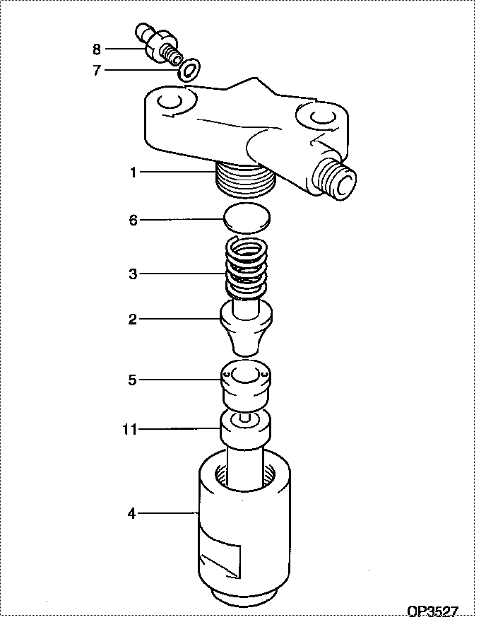
| 000. | [01] | 09350-00651 | HOLDER & NOZZLE SE | P821-80182 |
| 001. | [01] | 09311-10450 | BODY | P820-83811 |
| 002. | [01] | 09312-10030 | PIN, NOZZLE HOLDER | MM500135 |
| 003. | [01] | 09312-70020 | SPRING, NOZZLE HOL | ME022313 |
| 004. | [01] | 09316-40361 | NUT, NOZZLE RETAIN | P820-83840 |
| 005. | [01] | 09317-40011 | DISTANCE PIECE | ME703620 |
| 006. | [1C] | 09317-50120 | WASHER | MM500776 |
| 006. | [1C] | 09317-50130 | WASHER | MM500777 |
| 006. | [1C] | 09317-50140 | WASHER | MM500778 |
| 006. | [1C] | 09317-50150 | WASHER | MM500779 |
| 006. | [1C] | 09317-50160 | WASHER | MM500780 |
| 006. | [1C] | 09317-50170 | WASHER | MM500781 |
| 006. | [1C] | 09317-50180 | WASHER | MM500782 |
| 006. | [1C] | 09317-50190 | WASHER | MM500783 |
| 006. | [1C] | 09317-50200 | WASHER | MM500784 |
| 006. | [1C] | 09317-50110 | WASHER | MM500775 |
| 006. | [1C] | 09317-50100 | WASHER | MM500774 |
| 006. | [1C] | 09317-50010 | WASHER | MM500765 |
| 006. | [1C] | 09317-50020 | WASHER | MM500766 |
| 006. | [1C] | 09317-50030 | WASHER | MM500767 |
| 006. | [1C] | 09317-50040 | WASHER | MM500768 |
| 006. | [1C] | 09317-50050 | WASHER | MM500769 |
| 006. | [1C] | 09317-50060 | WASHER | MM500770 |
| 006. | [1C] | 09317-50070 | WASHER | MM500771 |
| 006. | [1C] | 09317-50080 | WASHER | MM500772 |
| 006. | [1C] | 09317-50090 | WASHER | MM500773 |
| 007. | [01] | 94901-80370 | WASHER, COPPER PLA | |
| 008. | [01] | 09314-10110 | NIPPLE, OIL LEAKAG | P820-83821 |
| 011. | [01] | 09340-00340 | NOZZLE ASSY | 09340-00340 |
Include in #3:
09350-00651
as HOLDER & NOZZLE SE
Cross reference number
| Part num | Firm num | Firm | Name |
| 09350-00651 | P821-80182 | HOLDER & NOZZLE SE |
Information:
TIMING PIN HOLE PLUG (Typical Example)
1. Plug.2. Rotate the crankshaft CLOCKWISE (as viewed from front of engine) until the timing pin drops into the timing slot in the fuel injection pump camshaft.3. Disconnect wire (2) from fuel shut off solenoid.
WIRE AND HOUSING
2. Wire. 3. Tachometer drive adapter housing.4. Remove the tachometer drive adapter housing (3).5. Use ratchet (4) and socket (5) to loosen automatic timing advance unit from fuel injection pump camshaft. Back off retaining bolt. The bolt will feel loose, then tighten up again when taper starts to separate from the camshaft.
REMOVING RETAINING BOLT
4. 8H8572 Ratchet. 5. 8S2357 Deep Well Socket.6. Remove the plug from timing hole (7) in the front cover and insert bolt (6). The cover retaining bolt from hole (8) may be used.
INSTALLING BOLT
6. 1D4539 Bolt [5/16 in. - 18 NC, 2.5 in. (63,5 mm) long]. 7. Timing hole. 8. Hole.7. Rotate crankshaft CLOCKWISE (as viewed from front of engine) until bolt (6) threads into the timing gear and is centered in timing hole (7). With timing pin in slot in fuel pump camshaft and the bolt (6) through the front cover and threaded into the timing gear, the fuel injection pump camshaft is timed to the engine.8. Remove the fuel injection pump housing retaining bolts (9).
RETAINING BOLTS
9. Retaining bolts.9. Remove the fuel injection pump housing and governor as a unit.
REMOVING HOUSINGInstall Fuel Injection Pump Housing and Governor
1. Install the fuel injection pump housing and governor as a unit. Install the fuel injection pump housing retaining bolts.2. Install the automatic timing advance unit retaining bolt and tighten retaining bolt to 35 2 lb. ft. (4.8 0.3 mkg).3. To check timing remove the timing pin and the bolt. Rotate the crankshaft two revolutions CLOCKWISE (as viewed from front of engine) and install the timing pin and bolt back in place. If the timing pin or bolt can not be installed, the fuel injection pump camshaft must be retimed.4. Remove the bolt (6) from the timing gear and install in hole (8). Install the plug into timing hole (7).5. Remove the timing pin from the timing slot in the fuel injection pump camshaft and install the plug in the timing hole.6. Install the tachometer drive adapter housing. Connect the wire to the fuel shut off solenoid.Disassemble Max-Min Governor
MAX-MIN GOVERNOR DISASSEMBLED
1. Seal. 2. Link. 3. Yoke. 4. Coned disc washer. 5. Washer.Assemble Max-Min Governor
MAX-MIN GOVERNOR
1. Seal. 2. Link. 3. Yoke. 4. Coned disc washer. 5. Washer.Install seal (1) with lip facing toward inside of governor housing.Link (2) must turn freely on yoke (3).Install coned disc washer (4) with concave side toward washer (5). The 1160 Engines, 5.0 in. (127.0 mm) stroke, do not have washer (4).
After disassembly and assembly, use the following initial settings to protect the engine from overspeed.
Disassemble Hydraulic Governor (9L9540 Governor)
HYDRAULIC GOVERNOR DISASSEMBLED
1. Seal. 2. Seal. 3. Weights.Assemble Hydraulic Governor (9L9540 Governor)
HYDRAULIC GOVERNOR
1. Seal. 2. Seal. 3. Weights.Lubricate seal (1) and all adjoining surfaces with clean engine oil (SAE 30).Install seal (2)