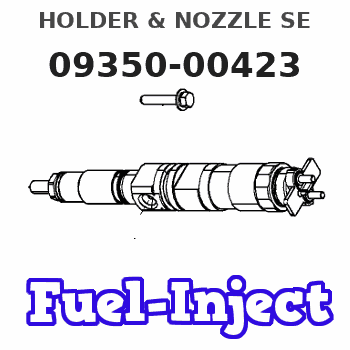
Information holder & nozzle se
Rating:
Components :
| 001. | HOLDER & NOZZLE SE | 09350-00423 |
Scheme ###:
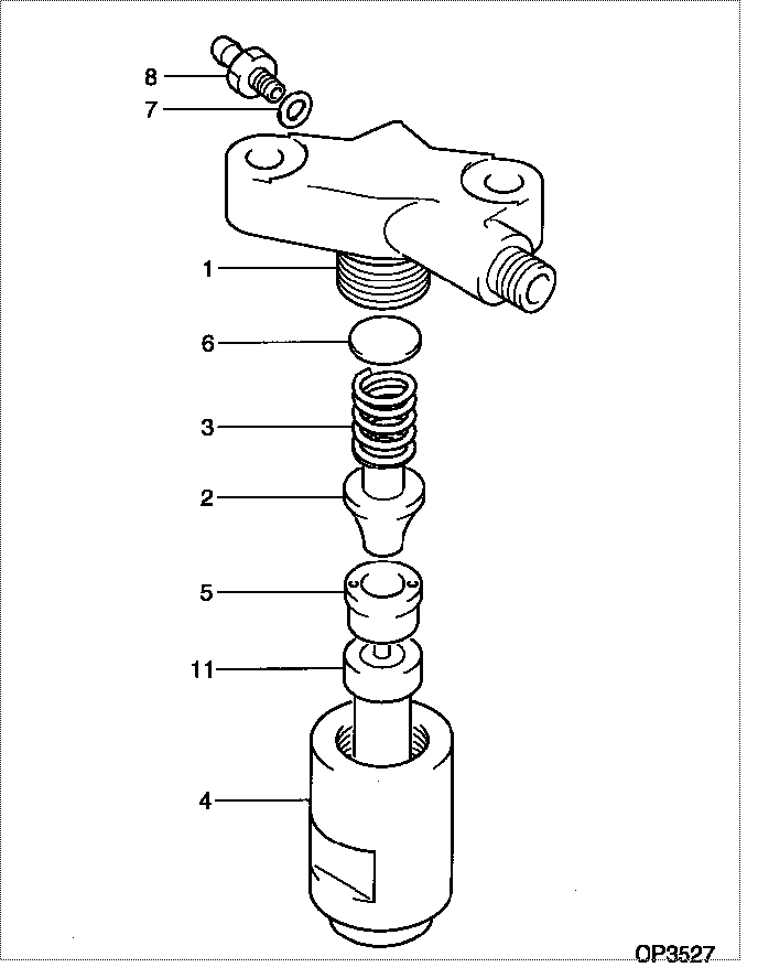
| 000. | [01] | 09350-00423 | HOLDER & NOZZLE SE | P820-80141 |
| 001. | [01] | 09311-10301 | BODY | P821-8353 |
| 002. | [01] | 09312-10030 | PIN, NOZZLE HOLDER | MM500135 |
| 003. | [01] | 09312-70020 | SPRING, NOZZLE HOL | ME022313 |
| 004. | [01] | 09316-40311 | NUT, NOZZLE RETAIN | P820-83740 |
| 005. | [01] | 09317-40011 | DISTANCE PIECE | ME703620 |
| 006. | [1C] | 09317-50120 | WASHER | MM500776 |
| 006. | [1C] | 09317-50130 | WASHER | MM500777 |
| 006. | [1C] | 09317-50140 | WASHER | MM500778 |
| 006. | [1C] | 09317-50150 | WASHER | MM500779 |
| 006. | [1C] | 09317-50160 | WASHER | MM500780 |
| 006. | [1C] | 09317-50170 | WASHER | MM500781 |
| 006. | [1C] | 09317-50180 | WASHER | MM500782 |
| 006. | [1C] | 09317-50190 | WASHER | MM500783 |
| 006. | [1C] | 09317-50200 | WASHER | MM500784 |
| 006. | [1C] | 09317-50110 | WASHER | MM500775 |
| 006. | [1C] | 09317-50100 | WASHER | MM500774 |
| 006. | [1C] | 09317-50010 | WASHER | MM500765 |
| 006. | [1C] | 09317-50020 | WASHER | MM500766 |
| 006. | [1C] | 09317-50030 | WASHER | MM500767 |
| 006. | [1C] | 09317-50040 | WASHER | MM500768 |
| 006. | [1C] | 09317-50050 | WASHER | MM500769 |
| 006. | [1C] | 09317-50060 | WASHER | MM500770 |
| 006. | [1C] | 09317-50070 | WASHER | MM500771 |
| 006. | [1C] | 09317-50080 | WASHER | MM500772 |
| 006. | [1C] | 09317-50090 | WASHER | MM500773 |
| 007. | [01] | 94901-80370 | WASHER, COPPER PLA | |
| 008. | [01] | 09314-10110 | NIPPLE, OIL LEAKAG | P820-83821 |
| 011. | [01] | 09340-00340 | NOZZLE ASSY | 09340-00340 |
Include in #3:
09350-00423
as HOLDER & NOZZLE SE
Cross reference number
| Part num | Firm num | Firm | Name |
| 09350-00423 | P820-80141 | HOLDER & NOZZLE SE |
Information:
WRENCH INSTALLED
1. 8S2243 Wrench. 2. Protective cap. 3. Retaining bushing.c. Install extractor (4).d. Remove retaining bushing (3) and wrench (1).e. Remove the seal and lift fuel injection pump (5) out of the housing. Keep components together and identified as to location.4. Remove rack (7) and rack bumper spring (6).
REMOVING PUMP
4. 8S2244 Extractor. 5. Fuel injection pump.
REMOVING RACK
6. Rack bumper spring. 7. Rack.5. Use magnet (8) to remove lifters (9). Identify lifters (9) and keep them with their respective fuel injection pumps.
REMOVING LIFTERS
8. 8S2293 Magnet. 9. Lifter.6. Remove the camshaft gear assembly retaining bolt (11) and lock. Remove plate assembly (10).
REMOVING PLATE ASSEMBLY
10. Plate assembly. 11. Bolt.7. Remove camshaft gear assembly (12) from camshaft (13).
REMOVING GEAR ASSEMBLY
12. Gear assembly. 13. Camshaft.
REMOVING BOLTS
14. Lock. 15. Bolts.8. Remove bolts (15) and lock (14).9. Remove camshaft retaining plate (16).
REMOVING RETAINING PLATE
16. Retaining plate.10. Remove camshaft (13).
REMOVING CAMSHAFT
13. Camshaft.11. Use camshaft bearing removal and installation group (17) to remove the camshaft bearings from the fuel injection pump housing.
REMOVING BEARINGS
17. 8S2241 Camshaft Bearing Removal and Installation Group.Assemble Fuel Injection Pump Housing
1. Use camshaft bearing removal and installation group (17) to install the camshaft bearings in the fuel injection pump housing. The camshaft bearings must be installed with the oil holes in the bearings in line with the oil hole in the housing. The front and rear bearings must be line bored after installation. To align oil holes and line bore the bearings, See Special Instruction (GMG00672).
INSTALLING BEARINGS
17. 8S2241 Camshaft Bearing Removal and Installation Group.2. Put clean engine oil (SAE 30) on the camshaft and install camshaft (13) in the fuel injection pump housing.
INSTALLING CAMSHAFT
13. Camshaft.3. Install the camshaft retaining plate (16).4. Install lock (14) and bolts (15).
INSTALLING RETAINING PLATE
16. Retaining plate.
INSTALLING BOLTS
14. Lock. 15. Bolts.5. Install camshaft gear assembly (12) on camshaft (13).
INSTALLING GEAR ASSEMBLY
12. Gear assembly. 13. Camshaft.6. Install plate assembly (10), retaining bolt (11), and lock.
INSTALLING PLATE ASSEMBLY
10. Plate assembly. 11. Bolt. Be sure to put the spacer on bolt (11).7. Use magnet (8) to install lifters (9). The lifters (9) must be installed in the same location from which they were removed.
INSTALLING LIFTERS
8. 8S2293 Magnet. 9. Lifters.8. Lubricate the rack with clean fuel oil. Install rack (7) with timing pin slot in rack toward front of the housing. Install rack bumper spring (6) so the large diameter of the bumper spring will be against the housing. If new lifters and pumps are to be installed it will be necessary to check and/or adjust the fuel pump timing dimension. See FUEL PUMP TIMING DIMENSION SETTING-OFF ENGINE in TESTING AND ADJUSTING section of the Service Manual.
INSTALLING RACK
6. Rack bumper spring. 7. Rack.9. Remove bolts (19) and rack cover (18).
RACK COVER
18. Rack cover. 19. Bolts.
TIMING PIN INSTALLED
20. Slot in rack. 21. 8S2291 or FT887 Timing Pin.10. The rack must be centered to install the fuel injection pumps. To center the rack, pull the rack toward the governor end of the housing until centering slot (20) in the rack is under the centering pin hole.