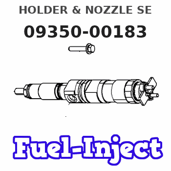
Information holder & nozzle se
Rating:
Components :
| 001. | HOLDER & NOZZLE SE | 09350-00183 |
Scheme ###:
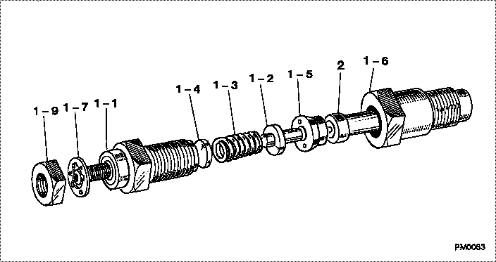
| 000. | [01] | 09350-00183 | HOLDER & NOZZLE SE | 04230-30120 |
| 001. | [01] | 09310-00183 | HOLDER ASSY, NOZZL | 04230-31200 |
| 001-001. | [01] | 09311-00241 | BODY SUB-ASSY, NOZ | 09311-00241 |
| 001-002. | [01] | 09312-10030 | PIN, NOZZLE HOLDER | MM500135 |
| 001-003. | [01] | 09312-70020 | SPRING, NOZZLE HOL | ME022313 |
| 001-004. | [1C] | 09317-50120 | WASHER | MM500776 |
| 001-004. | [1C] | 09317-50130 | WASHER | MM500777 |
| 001-004. | [1C] | 09317-50140 | WASHER | MM500778 |
| 001-004. | [1C] | 09317-50150 | WASHER | MM500779 |
| 001-004. | [1C] | 09317-50160 | WASHER | MM500780 |
| 001-004. | [1C] | 09317-50170 | WASHER | MM500781 |
| 001-004. | [1C] | 09317-50180 | WASHER | MM500782 |
| 001-004. | [1C] | 09317-50190 | WASHER | MM500783 |
| 001-004. | [1C] | 09317-50200 | WASHER | MM500784 |
| 001-004. | [1C] | 09317-50110 | WASHER | MM500775 |
| 001-004. | [1C] | 09317-50100 | WASHER | MM500774 |
| 001-004. | [1C] | 09317-50010 | WASHER | MM500765 |
| 001-004. | [1C] | 09317-50020 | WASHER | MM500766 |
| 001-004. | [1C] | 09317-50030 | WASHER | MM500767 |
| 001-004. | [1C] | 09317-50040 | WASHER | MM500768 |
| 001-004. | [1C] | 09317-50050 | WASHER | MM500769 |
| 001-004. | [1C] | 09317-50060 | WASHER | MM500770 |
| 001-004. | [1C] | 09317-50070 | WASHER | MM500771 |
| 001-004. | [1C] | 09317-50080 | WASHER | MM500772 |
| 001-004. | [1C] | 09317-50090 | WASHER | MM500773 |
| 001-005. | [01] | 09317-40011 | DISTANCE PIECE | ME703620 |
| 001-006. | [01] | 09316-40420 | NUT, NOZZLE RETAIN | MM500138 |
| 001-007. | [01] | 09324-50110 | WASHER | MM500139 |
| 001-009. | [01] | 94905-02480 | NUT, HEXAGON | MM500141 |
| 002. | [01] | 09340-00090 | NOZZLE ASSY | 04230-33120 |
Include in #3:
09350-00183
as HOLDER & NOZZLE SE
Cross reference number
| Part num | Firm num | Firm | Name |
| 09350-00183 | 04230-3012 | HOLDER & NOZZLE SE |
Information:
start by:a) remove turbocharger 1. Put the turbocharger in position on tool (A).2. Put a mark on the compressor cover and housings for installation purpose.3. Remove bolts (1) and plates from compressor housing.4. Remove the compressor housing. 5. Remove bolts (2) and locks from turbine housing. 6. Remove cartridge (3) from turbine housing.7. Install tool (B) in tool (C). Install cartridge in tool (C).8. Remove nut (4) from the compressor wheel.
When the nut is loosened, do not put a side force on the shaft.
9. Install tool (D) on an oil heater. Heat the oil to 350°F (177°C). Install the cartridge on tool (D) with only the compressor wheel in the hot oil. Keep the compressor wheel in the hot oil for ten minutes. 10. Put tool (D) and cartridge on tool (E) under a press. Install driver (F) and push the shaft out of the compressor wheel. Step 10 must be done before the compressor wheel gets cold.11. Remove compressor wheel and shroud. Remove turbine wheel and shaft. 12. Remove the four bolts (5) and locks from plate (6). 13. Remove plate (6), spacer, collar and thrust bearing from cartridge.14. Remove seal from plate and ring from spacer. 15. Remove bearing (7), washer (11) and snap ring (8) from compressor side of cartridge.16. Remove snap ring (13), washer (10), bearing (12) and snap ring (9) from turbine side of cartridge.17. Check all the parts of the turbocharger for damage. If the parts have damage, use new parts for replacement. See SPECIAL INSTRUCTION, Form No. SMHS6854 for TURBOCHARGER RECONDITIONING. Also see GUIDELINE FOR REUSABLE PARTS, Form No. SEBF8018.Assemble Turbocharger (Airesearch T18)
1. Make sure all oil passages are open and clean. Put clean engine oil on all parts before assembly 2. Install snap ring (6), bearing (3), washer (7) and snap ring (4) in turbine side of cartridge. Install the two snap rings with tool (A). Install the snap rings with the rounded edge toward the bearing.3. Install snap ring (2), washer (5) and bearing (1) in compressor side of cartridge. 4. Install seal (12) on plate (8) and ring (9) on spacer.5. Install collar (10) in plate and spacer (11) in collar. 6. Install thrust bearing (13) with the three radial grooves toward the outside.7. Install plate (8), bolts and locks. Tighten bolts to a torque of 35 5 lb. in. (4.0 0.6 N m). Put 6V2055 High Vacuum Grease in the groove for seal ring (14) at assembly to one half or more of the depth of the groove all the way around.8. Install ring (14) on turbine wheel.9. Install turbine wheel and shaft in cartridge. Be careful not to break ring (14) when installing shaft. 10. Put cartridge on tool (C) and tool (C) on tool (B). Some compressor wheels (15) can be installed at room temperature. If the compressor wheel will go on the turbine shaft freely to within .31 in. (7.9 mm) of the seal carrier the compressor wheel can be installed at