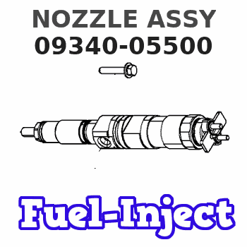
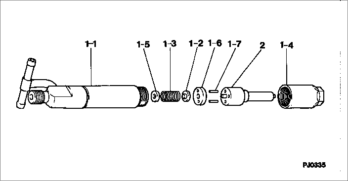
Information nozzle assy
Nozzle Type:
ND-DLLA160P50
MITSUBISHI CANTER 4D31
MITSUBISHI CANTER 4D32
MITSUBISHI CANTER 4D33
MITSUBISHI CANTER 4D34T2
Rating:
Compare Prices: .
As an associate, we earn commssions on qualifying purchases through the links below

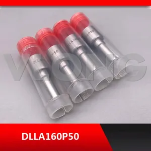
DLLA160P50 Diesel Injectors Nozzle DLLA 160P50 093400-5500 0934005500 (Quantity 24 Pieces/Lot)
PLDIAGBP It can accurately control the fuel injection volume, ensure the combustion efficiency of the engine, and enhance the power output as well as fuel economy. || It can accurately control the fuel injection volume, ensure the combustion efficiency of the engine, and enhance the power output as well as fuel economy. || It can withstand the impact of high-pressure fuel and maintain structural integrity and stable performance. || It generates little noise during operation, without affecting the driving experience. || DLLA160P50 Diesel Injectors Nozzle DLLA 160P50 093400-5500 0934005500 (Quantity 24 Pieces/Lot)
PLDIAGBP It can accurately control the fuel injection volume, ensure the combustion efficiency of the engine, and enhance the power output as well as fuel economy. || It can accurately control the fuel injection volume, ensure the combustion efficiency of the engine, and enhance the power output as well as fuel economy. || It can withstand the impact of high-pressure fuel and maintain structural integrity and stable performance. || It generates little noise during operation, without affecting the driving experience. || DLLA160P50 Diesel Injectors Nozzle DLLA 160P50 093400-5500 0934005500 (Quantity 24 Pieces/Lot)

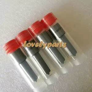
4PCS Diesel Spare Parts Fuel Injectors Sparyer Nozzles Tips DLLA160P50 D LLA 160 P50 0934005500 093400-5500
CIGFCDGF 4PCS Diesel Spare Parts Fuel Injectors Sparyer Nozzles Tips DLLA160P50 D LLA 160 P50 0934005500 093400-5500 || Product Numbers: Includes model numbers DLLA160P50 0934005500 093400-5500 For easy user matching and replacement || Function Description: Delivers precise fuel injection performance Supports efficient engine operation needs || Installation Convenience: Designed with standard interfaces Direct replacement for old parts Reduces installation time and complexity || Technical Features: Optimized spray angle Enhances fuel atomization Promotes more complete combustion process
CIGFCDGF 4PCS Diesel Spare Parts Fuel Injectors Sparyer Nozzles Tips DLLA160P50 D LLA 160 P50 0934005500 093400-5500 || Product Numbers: Includes model numbers DLLA160P50 0934005500 093400-5500 For easy user matching and replacement || Function Description: Delivers precise fuel injection performance Supports efficient engine operation needs || Installation Convenience: Designed with standard interfaces Direct replacement for old parts Reduces installation time and complexity || Technical Features: Optimized spray angle Enhances fuel atomization Promotes more complete combustion process

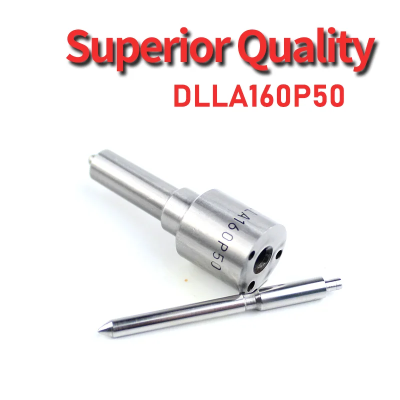
093400-5500 Fuel Injection Nozzle 12Pcs
DFGUFG [Product compatibility]: The OE number of this product is 093400-5500 || [Enhanced Fuel Efficiency & Power Output: Precision-engineered fuel injectors optimize spray patterns for improved combustion efficiency, directly boosting mileage while maintaining stable engine performance across all RPM ranges || [Easy to install and affordable]: Each fuel injector meets factory standard specifications, is simple and convenient to install, has higher combustion efficiency, and can effectively reduce fuel consumption || [High-quality materials for better performance]: The injectors are made of high-quality materials and advanced manufacturing processes to ensure durability and service life, allowing your engine to run smoothly for a long time || [Guaranteed Engine Performance]: This product is one of the key components of electronic fuel injection engines, helping to improve engine performance
DFGUFG [Product compatibility]: The OE number of this product is 093400-5500 || [Enhanced Fuel Efficiency & Power Output: Precision-engineered fuel injectors optimize spray patterns for improved combustion efficiency, directly boosting mileage while maintaining stable engine performance across all RPM ranges || [Easy to install and affordable]: Each fuel injector meets factory standard specifications, is simple and convenient to install, has higher combustion efficiency, and can effectively reduce fuel consumption || [High-quality materials for better performance]: The injectors are made of high-quality materials and advanced manufacturing processes to ensure durability and service life, allowing your engine to run smoothly for a long time || [Guaranteed Engine Performance]: This product is one of the key components of electronic fuel injection engines, helping to improve engine performance
You can express buy:
USD 30.8
14-06-2025
14-06-2025
4Pcs Injector Nozzle NP-DLLA160P50 093400-5500 for MITSUBISHI 4D31 4D33 4D34
USD 23.75
19-05-2025
19-05-2025
4PCS Super Quality New Diesel Spare Parts Fuel Injectors Sparyer Nozzles Tips DLLA160P50 D LLA 160 P50 0934005500 093400-5500
USD 4.1
13-05-2025
13-05-2025
DLLA160P50 Diesel engine nozzle 093400-5500 is suitable for all diesel 495 diesel injector P series oil head DTJA28Z31
Images:
USD 22

[13-May-2025]
USD 16.98

[03-May-2025]
USD 6

[15-Jul-2022]
USD 20

[17-Apr-2019]
Include in #3:
Cross reference number
| Part num | Firm num | Firm | Name |
| 09340-05500 | ME703687 | NOZZLE ASSY | |
| ME703687 | MITSUBISHI | NOZZLE ASSY |
Information:
Start By:a. remove valve covers 1. Remove bolts (1) that hold the valve cover bases to the cylinder head assembly. Remove valve cover bases (2). 2. Use tool (A) to loosen fuel injection line (3) from fuel injection nozzle (4). 3. Use tool (B) to loosen the nut at the fuel injection line adapter end. Remove inner fuel injection lines (3). Install caps and plugs on all fuel injection line openings to keep dirt out of the fuel system. 4. Remove bolts (5) that hold the rocker shaft assemblies to the cylinder head assembly.5. Remove rocker shaft assemblies (6). 6. Put identification marks on the push rods as to their location in the engine. Remove push rods (7). 7. Put identification marks on the bridges as to their location in the engine. Remove bridges (8) from the dowels on the cylinder head assembly.Install Rocker Shaft Assemblies And Push Rods
1. Put clean engine oil on the bridges and dowels. Install the original bridges in their respective locations. New bridges can be mixed.2. Install bridges (8) on the bridge dowels. While firmly pressing 0.5 to 4.5 kg (1 to 10 lb.) straight down on the top contact surface of the bridge, turn the adjusting screw clockwise until contact is made with the valve stem. Turn the screw an additional 20° to 30° (1/3 to 1/2 of 1 hex on nut). This will straighten the dowel in the guide and compensate for the slack in the threads. Hold the adjusting screw in this position, and tighten the locknut to a torque of 30 4 N m (22 3 lb.ft.). Install original push rods in their respective locations in the engine. New push rods can be mixed.3. Install push rods (7). 4. Put rocker shaft assemblies (6) in position on the cylinder head assembly.5. Put clean engine oil on the threads of bolts (5) that hold the shaft assemblies in place. Tighten the bolts first to a torque of 270 25 N m (200 18 lb.ft.). Start with the bolt in the center of the rocker shaft assembly. Tighten the bolts again to a torque of 450 20 N m (330 15 lb.ft.). Tighten the bolts again by hand to a torque of 450 20 N m (330 15 lb.ft.).
Do not cause damage to the O-ring seals on the inner fuel lines.
6. Install inner fuel injection lines (3). Tighten the fuel injection line adapter nuts (9) to a torque of 40 7 N m (30 5 lb.ft.) with tool (B).7. Tighten fuel injection line nut (10) to a torque of 40 7 N m (30 5 lb.ft.) with tool (A).8. Make adjustments to the valves until the intake valve clearance is 0.38 mm (.015 in.) and the exhaust valve clearance is 0.76 mm (.030 in.). See Valve Clearance Setting in Testing And Adjusting. Tighten the locknut to a torque of 30 4 N m (22 3 lb.ft.) and