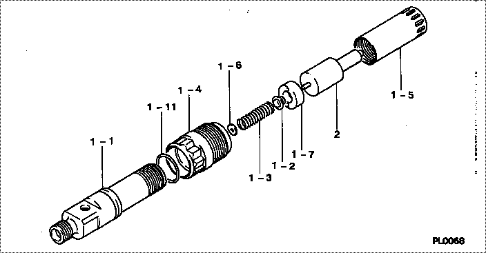
Information nozzle assy
Nozzle Type:
ND-DLLA158P44
JOHN DEERE TRACTOR 6466A
Rating:
Include in #3:
Cross reference number
| Part num | Firm num | Firm | Name |
| 09340-05440 | RE30085 | NOZZLE ASSY | |
| RE30085 | JOHN DEERE | NOZZLE ASSY |
Information:
Turn the engine to (TDC) top center compression stroke for the No. 1 piston and install crankshaft flywheel timing pin. This will help when timing the camshaft when installing.
Wire used to hold cam roller followers up off camshaft. It is not necessary to remove the cylinder head. With the cylinder head in place, just wire the cam roller followers up off the camshaft and then remove the camshaft. 1. Remove camshaft retainer bolt (1) and remove camshaft assembly (2). The following steps are for the installation of the camshaft assembly.
Typical Example When installing the camshaft, rotating it both clockwise and counter clockwise directions will help prevent it from binding in the bearing bores.2. Put engine oil on the lobes and journals of the camshaft. Carefully install the camshaft. When installing the camshaft, be sure the number one cylinder is at (TDC) top dead center of the compression stroke with the timing pin installed in the flywheel. Camshaft timing is very important. Cam gear timing marks must line up with idler gear timing marks as illustrated. For more information about timing of engine, refer to Specifications module, Form No. SENR3908.
Camshaft Timing3. With the camshaft properly timed and positioned, install retaining bolt (1). Tighten bolt (1) to a torque of 48 7 N m (37 5 lb ft). Remove the wire that was used to hold the cam roller followers up off the camshaft.End By:a. install fuel transfer pumpb. install front coverc. install front pulley and damperd. install fuel injectorse. install rocker arm assemblies and push rodsDisassembly & Assembly of Camshaft And Gear Assembly
Start By:a. remove camshaft assembly 1. Wrap camshaft portion of camshaft and gear assembly (1) with paper towels to protect the camshaft from being damaged. 2. Remove six bolts (2). Remove timing/speed sensor ring gear (3). The timing/speed ring gear is located on gear (4) by dowel (6). Care must be taken not to damage timing/speed sensor ring gear (3) when removing. Using the prybar, work around the ring gear and pry the ring gear off a little at a time.
Care must be taken not to allow the camshaft to fall to the floor when pressing it from the gear. Also be sure that a camshaft lobe does not catch on the press plates.
3. Place camshaft and gear assembly (1) in a press. Press camshaft (5) from gear (4). The following steps are for the assembly of the camshaft and the gear assembly. 4. To install gear (4) on camshaft (5), place gear in the oven at 300°C (572°F) for 30 minutes and then install. Be sure the woodruff key is properly aligned and the gear is flush with the camshaft flange. 5. Align timing gear sensor ring gear (3) with dowel (6). "Front" is marked and visible when installing timing/speed ring gear sensor. Care must be taken not to damage the timing/speed sensor ring gear when installing. Using a mallet tap around the ring gear and drive it on a little at a