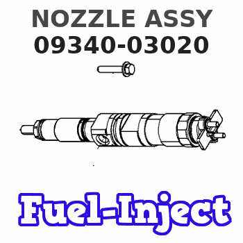
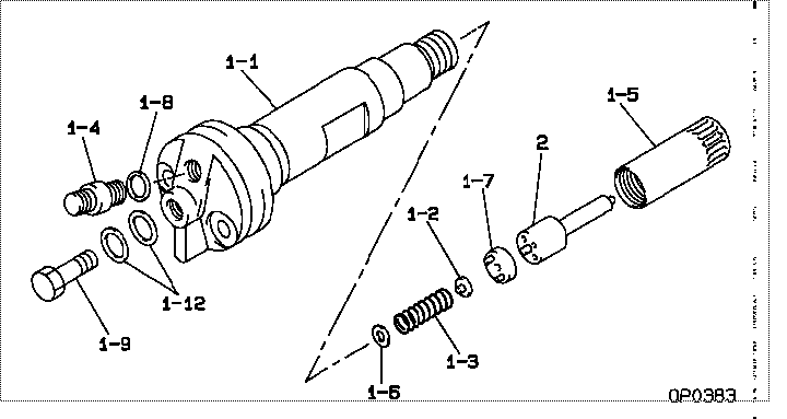
Information nozzle assy
Nozzle Type:
ND-DLLA150SND302
KOMATSU INDUSTRIAL S6D125
Rating:
Compare Prices: .
As an associate, we earn commssions on qualifying purchases through the links below

12PCS XDEP Factory Price DNSD Type Fuel Injector Nozzle 093400-3020 Part No.DLLA150SND302
XDEP Part NO.:DLLA150SND302 || Application: Diesel Fuel Injection System, DNSD Nozzle Replace for Injector || Guarantee: 6 Months Warranty. 100% Tested Before Shipping to Ensure Product Safety, Stability and Durability || Function: High-Quality Material for Long-Lasting Durability. Perfect Match for the Injector and Easy to Install || Tips: Please be Sure to Compare Carefully with Photos and Check Part Number before Buying Items, If You are not Sure This Part is Suitable, Please Feel Free to Contact Us, We'll Reply You as Soon as Possible.
XDEP Part NO.:DLLA150SND302 || Application: Diesel Fuel Injection System, DNSD Nozzle Replace for Injector || Guarantee: 6 Months Warranty. 100% Tested Before Shipping to Ensure Product Safety, Stability and Durability || Function: High-Quality Material for Long-Lasting Durability. Perfect Match for the Injector and Easy to Install || Tips: Please be Sure to Compare Carefully with Photos and Check Part Number before Buying Items, If You are not Sure This Part is Suitable, Please Feel Free to Contact Us, We'll Reply You as Soon as Possible.
Include in #3:
Cross reference number
| Part num | Firm num | Firm | Name |
| 09340-03020 | 61511-2312 | NOZZLE ASSY | |
| 61511-23120 | KOMATSU | NOZZLE ASSY |
Information:
Introduction
Table 1
Revision History
Revision Summary of Changes
01 Changes were made to Illustration 2. This Special Instruction contains the rework procedure for Diesel Exhaust Fluid (DEF) injector clearance hole on the machines listed above.Do not perform any procedure in this Special Instruction until you have read the information and you understand the information.Reference Section
Reference: Operation and Maintenance Manual , SEBU9084 , "Loader Lift Arm Brace Operation"Safety Section
Do not operate or work on this product unless you have read and understood the instruction and warnings in the relevant Operation and Maintenance Manuals and relevant service literature. Failure to follow the instructions or heed the warnings could result in injury or death. Proper care is your responsibility.
Failure to follow all safety guidelines prescribed in this document and by governing authorities and regulatory agencies may result in severe injury or death of personnel or machine damage.
When removing a major component or attachment, ensure that it is properly blocked or secured before removing mounting hardware. An assembly that is disconnected without proper blocking may shift or fall, resulting in serious injury or death of personnel or machine damage.
Personal injury or death can result from improper maintenance procedures. To avoid injury or death, follow the procedures exactly as stated below.
Before servicing/performing maintenance on the machine, electrical power must be physically disconnected; battery plugs must be disconnected from the batteries, or the trailing cable must be unplugged, and warning tags and padlocks shall be applied by a certified electrician. Certified electricians shall perform or direct any electrical work, including any energized testing, repair work in controllers, motors, or other approved compartments, and shall insure that all compartments are properly closed and inspected prior to re-energization. All applicable lock out and tag out procedures must be followed.
Do not operate the machine if any guards or covers are missing or inadequately secured. Personnel could be seriously injured or machine damage may occur.
Observe the safe working load limits of all lifting and blocking devices and keep a safe distance from suspended/blocked loads. Personnel may be seriously injured or killed by falling loads.
Required Parts
Table 2
Required Parts
Item Qty Part Number Part Name
1 1 574-7991 Film Field Rework Procedure
Illustration 1 g06471195
DEF injector hose connector contacting the clearance hole
Visually inspect the DEF injector clearance hole for evidence of rub and wear for the DEF injector hose connector.
Illustration 2 g06480781
Clearance hole before grinding
Illustration 3 g06471198
Detail of area A
(D1) 12.1 mm (0.48 inch)
(D2) 75 mm (2.9 inch)
(D3) 50 mm (1.96 inch)