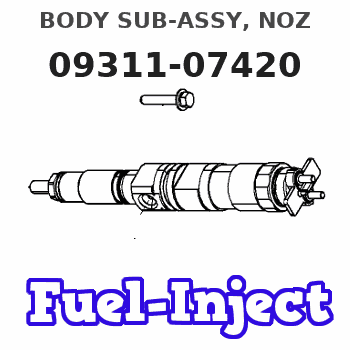
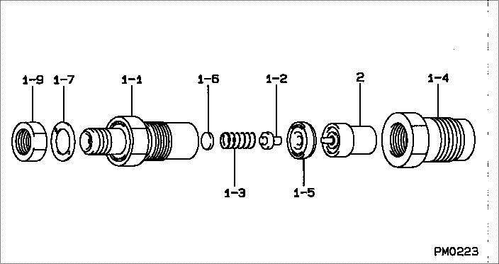
Information body sub-assy, noz
Rating:
Include in #3:
Cross reference number
| Part num | Firm num | Firm | Name |
| 09311-07420 | 23626-5421 | BODY SUB-ASSY, NOZ | |
| 23626-54210 | TOYOTA | BODY SUB-ASSY, NOZ |
Information:
Removal
IMPORTANT: Disconnect battery negative (-) cable at the battery.Disconnect battery wires from terminals and field wire connector.Loosen bolts attaching alternator to mounting brackets and remove drive belt.Remove attaching bolts and alternator.
Fig. 1-Delco-Remy AlternatorRepair
Fig. 2-Separate FramesRemove through bolts. Pry stator and slip ring end frame assembly from the rotor and drive end frame assembly. After disassembly, place a piece of pressure-sensitive tape over the slip ring end bearing to prevent entry of dirt or foreign material.Drive End Frame Bearing
Fig. 3-A-209 ToolRemove pulley, fan, and collar. Then separate the drive end frame from the rotor shaft. Remove the retainer plate and press bearing from the end frame (Fig. 3). The bearing may be reused if it is in satisfactory condition. Clean the bearing and fill it 1/4 full with Delco-Remy Lubricant No. 1948791 before assembly. Overfilling bearing may cause bearing to overheat.
Fig. 4-A-203 and A-207 ToolInstall bearing (Fig. 4). Install new retainer plate if felt seal is hard or excessively worn. Fill cavity between retainer plate and the bearing with 1948791 Lubricant. Install rotor, collars, fan and pulley. Tighten nut to 40 to 60 lb-ft (54 to 81 Nm) (6 to 8 kg-m) torque.Slip Ring End Bearing
Fig. 5-A-209 ToolReplace the slip ring end bearing if its grease supply is exhausted or if the bearing is defective. Do not attempt to relubricate bearing. Press bearing from outside to inside of frame (Fig. 5).
Fig. 6-Install Slip Ring End BearingTo install a new bearing, place a flat plate over the bearing and press it in from the outside towards the inside of the frame until the bearing is flush with the outside of the end frame (Fig. 6). Support the inside of the frame with a cylinder to prevent breakage of the end frame.Stator and Slip Ring End Frame
Fig. 7-Stator Ground CheckBefore removing brushes or diode trio, check for grounds between points A to C and B to C (Fig. 7) with an ohmmeter, using the lowest range scale. Then reverse the lead connections.If both A to C readings or both B to C readings are the same, the brushes may be grounded because of a defective insulating washer and sleeve at the two screws. If the screw assembly is not damaged, the regulator or diode trio is defective.Diode Trio
Fig. 8-Diode TrioTo check the diode trio, first remove the stator. Then remove the diode trio, noting the insulator positions. With an ohmmeter, check between points A (Fig. 8) and D and then reverse the ohmmeter lead connections. A good diode trio will give one high and one low reading.