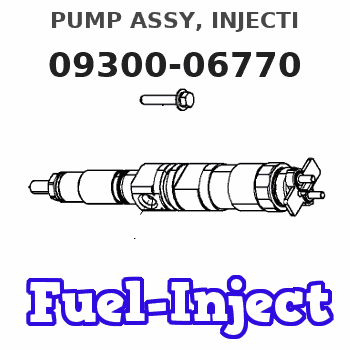
Information pump assy, injecti
Nozzle:
0935007500
Rating:
KIT List:
| Governor assy, mec | 1908900720 |
| Timer assy, automa | No Application |
| Pump assy, fuel fe | 1922900060 |
| Body assy, injecti | 1904400380 |
Components :
| 001. | PUMP ASSY, INJECTI | 09300-06770 |
| 002. | GOVERNOR ASSY, MEC | 09130-07450 |
| 003. | LEVER SET | 09129-10460 |
| 004. | COMPENSATOR SUB-AS | 19260-01330 |
| 005. | TIMER ASSY, AUTOMA | 09180-03754 |
| 006. | PUMP ASSY, FUEL FE | 09210-02840 |
| 007. | BODY ASSY, INJECTI | 19010-00962 |
Scheme ###:
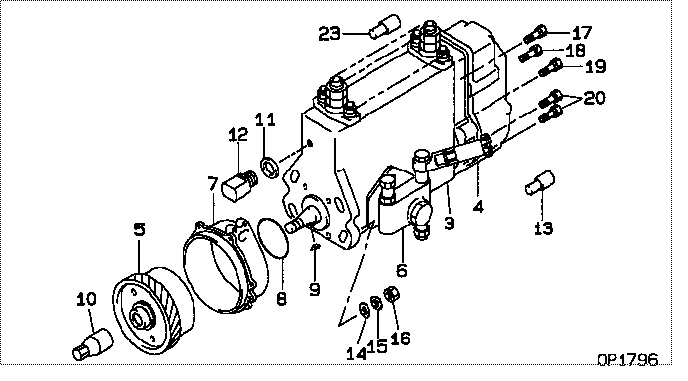
| 000. | [01] | 09300-06770 | PUMP ASSY, INJECTI | ME223026 |
| 003. | [01] | 19010-00962 | BODY ASSY, INJECTI | ME736900 |
| 004. | [01] | 09130-07450 | GOVERNOR ASSY, MEC | ME743845 |
| 005. | [01] | 09180-03754 | TIMER ASSY, AUTOMA | ME736904 |
| 006. | [01] | 09210-02840 | PUMP ASSY, FUEL FE | ME736506 |
| 007. | [01] | 09006-00570 | COVER SUB-ASSY, TI | ME743445 |
| 008. | [01] | 94914-03690 | O-RING | ME736557 |
| 009. | [01] | 90458-05750 | KEY, WOODRUFF | ME702920 |
| 010. | [01] | 09001-20360 | NUT, TIMER ROUND | ME736909 |
| 011. | [01] | 94901-81550 | WASHER, COPPER PLA | ME039681 |
| 012. | [01] | 09001-80410 | COVER, CONTROL RAC | ME736558 |
| 013. | [01] | 09028-50021 | CAP | ME035845 |
| 014. | [04] | 94901-15020 | WASHER, STEEL PLAT | MH005068 |
| 015. | [04] | 90258-10001 | WASHER, SPRING | MC327716 |
| 016. | [04] | 91266-10081 | NUT, HEXAGON | MF430122 |
| 017. | [02] | 94904-76880 | BOLT, W/WASHER | ME728977 |
| 018. | [01] | 94904-76910 | BOLT, W/WASHER | ME728980 |
| 019. | [01] | 94904-76900 | BOLT, W/WASHER | ME728979 |
| 020. | [04] | 94904-76890 | BOLT, W/WASHER | ME728978 |
| 023. | [01] | 09028-50050 | CAP | ME076458 |
Include in #3:
09300-06770
as PUMP ASSY, INJECTI
Cross reference number
| Part num | Firm num | Firm | Name |
| 09300-06770 | ME223026 | PUMP ASSY, INJECTI | |
| ME223026 | MITSUBISHI | PUMP ASSY, INJECTI |
Information:
start by: a) remove oil pump 1. Check each main bearing cap (1) for its location on the engine. Each cap has a number which gives its location of that cap.2. Remove the nuts that hold the main bearing cap in position and remove bearing cap (1) from the engine. Remove the lower half of the main bearings from the cap. 3. Turn the crankshaft until tool (A) can be installed in oil hole of the crankshaft. Turn the crankshaft in the direction which will push the upper main bearing out, tab end first.
If the crankshaft is turned in the wrong direction, the tab of the bearing will be pushed between the crankshaft and the cylinder block. This will cause damage to the crankshaft and block.
4. Put clean engine oil on the lower bearings. Install lower bearings in the bearing caps.5. Put clean engine oil on the upper bearings. Install upper bearings in the cylinder block with tool (A). Be sure the tab on the back of the bearings fits in the grooves of the caps and cylinder block. When the bearing clearance is checked the crankshaft will have to be lifted up against the upper halves of the main bearings and held to get a measurement with wire (2). The wire will not hold the weight of the crankshaft.6. Check the bearing clearance with wire (2) as follows: a) Put a piece of 5B1161 Wire (2) in position across the lower half of the main bearing.b) Install the cap, bearing and wire (2) in the block. Make sure the bearing location tangs are on the same side of the block.c) Tighten the nuts that hold the main bearing cap to a torque of 75 5 lb. ft. (100 7 N m) plus 120° 5°.7. Remove the main bearing cap and measure thickness (bearing clearance). The bearing clearance must be .0035 to .0066 in. (0.089 to 0.168 mm) and must not be more than .010 in. (0.25 mm). 8. If bearing clearance is correct, install bearing and cap on the block. Put engine oil on crankshaft and main bearing cap. Tighten nuts to a torque of 75 5 lb. ft. (100 7 N m) plus 120° 5°.end by: a) install oil pump