Information pump assy, injecti
Rating:
Scheme ###:

| 000. | [01] | 09300-06690 | PUMP ASSY, INJECTI | 22010-9060 |
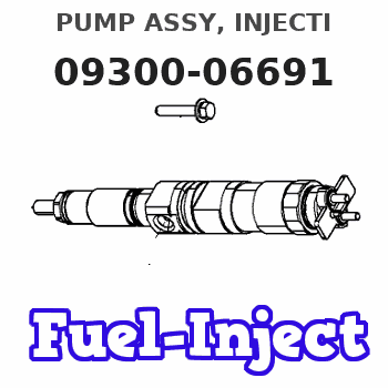
| 000. | [01] | 09300-06691 | PUMP ASSY, INJECTI | 22010-E0170-A |
| 004. | [01] | 09031-00390 | VALVE ASSY, OVERFL | S2210-71500-A |
| 005. | [03] | 94901-02480 | WASHER | S2284-71940-A |
| 006. | [01] | 09001-80090 | COVER, CONTROL RAC | S2211-41250-A |
| 007. | [04] | 94904-72690 | BOLT, W/WASHER | S2281-52410-A |
| 008. | [01] | 94904-74850 | BOLT, W/WASHER | S2281-52900-A |
| 009. | [01] | 09006-00631 | COVER SUB-ASSY, TI | 22650-E0040 |
| 010. | [01] | 91418-06201 | BOLT, W/WASHER | S2281-51290-A |
| 011. | [01] | 94904-73910 | BOLT, W/WASHER | S2281-52820-A |
| 012. | [01] | 09210-01510 | PUMP ASSY, FUEL FE | S2257-01240-A |
| 013. | [01] | 09130-07260 | GOVERNOR ASSY, MEC | S2231-07000-A |
| 014. | [01] | 09001-20220 | NUT, TIMER ROUND | S2251-11060-A |
| 015. | [01] | 09180-04160 | TIMER ASSY, AUTOMA | S2251-03070-A |
| 016. | [01] | 09028-50050 | CAP | S2232-31430-A |
| 017. | [01] | 90458-04051 | KEY, WOODRUFF | S2289-51080-A |
| 018. | [01] | 19010-01780 | BODY ASSY, INJECTI | S2211-03680-A |
| 021. | [01] | 09028-50030 | CAP | S2232-31210-A |
| 022. | [04] | 91266-10081 | NUT, HEXAGON | S2282-51490-A |
| 023. | [04] | 94901-15020 | WASHER, STEEL PLAT | S2287-71551-A |
| 024. | [04] | 90258-10001 | WASHER, SPRING | S2821-91120-A |
| 025. | [01] | 94901-40210 | WASHER, COUNTERSUN | S2286-71320-A |
| 026. | [01] | 94933-03610 | TUBE, RUBBER | S2243-51210-A |
| 027. | [01] | 94935-03042 | CLIP, CORD | S7990-42030-A |
Include in #3:
09300-06691
as PUMP ASSY, INJECTI
Cross reference number
| Part num | Firm num | Firm | Name |
| 09300-06691 | 22010-E017 | PUMP ASSY, INJECTI |
Information:
Safety
The safety symbols or in the manual indicate an item or procedure where the use of caution and safety is necessary. ALWAYS heed these symbols.Your safety and that of others is always the number one consideration when working around machines. Safety is a matter of thoroughly understanding the job to be done and the application of good common sense; not just a matter of "do's" and don'ts."Cleanliness
Whenever hydraulic, fuel, lubricating oil or air lines are disconnected, clean the point of disconnection and the adjacent area. As soon as the disconnection is made, cap, plug or tape the line or opening to prevent entry of foreign material. The same recommendations for cleaning and covering supply when access covers or inspection plates are removed.Clean and inspect all parts. Be sure all passages and holes are open. Cover all parts to keep them clean. Be sure parts are clean when installed. Leave new parts in their containers until ready for assembly.Removal And Installation
Unless otherwise specified, all removals should be accomplished using an adjustable lifting beam. All supporting members (chains and cables) should be parallel to each other and as near perpendicular as possible to the top of the object being lifted. When it is necessary to remove a component on an angle, remember that the capacity of an eyebolt diminishes as the angle between the supporting members and the object becomes less than 90°. Eyebolts and brackets should never be bent and should only have stress in tension. A length of pipe and a washer can be used, as shown, to help relieve these stresses on eyebolts.Forged eyebolts are available. Each size eyebolt has a maximum load recommendation. Some removals require the use of lifting fixtures to obtain proper balance and to provide safe handling.If a part resists removal, check to be certain all nuts and bolts have been removed and that an adjacent part is not interfering.Disassembly And Assembly
When assembling a machine, complete each step in turn. Do not partially assemble one part and start assembling some other part. Make all adjustments as recommended. Always check the job after it is completed to see nothing has been overlooked.First Operation Of A Rebuilt Engine
Use the following procedure:1. If the diesel engine has a starting engine, use the starting engine to make the engine turn for 10 minutes.2. Start the diesel engine, then run the engine at low RPM for 10 minutes. Make correct low idle governor adjustment. Check the pressure of the cooling system and the lubrication system. Look for leaks of water and of oil.3. Run the engine at 3/4 of full RPM with 1/2load for 15 minutes.4. Run the engine at full RPM and make correct high idle governor adjustment, then run engine at full RPM and with full load for 30 minutes.Service Tools
Puller Assembly (2 or 3 Arm)
Two or three arm puller assemblies can be used to remove gears, bearing cages, hubs, bearings, shafts, etc.
1-Puller.
1-Puller. 2-Step Plate.
1-Puller. 2-Step Plate.Bearing Pulling Attachment
Bearing Pulling Attachments can be used