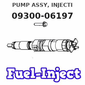
Information pump assy, injecti
Rating:
Scheme ###:

| 000. | [01] | 09300-06197 | PUMP ASSY, INJECTI | 33100450111 |
| 003. | [01] | 19010-00602 | BODY ASSY, INJECTI | |
| 003. | [01] | 19010-01600 | BODY ASSY, INJECTI | |
| 003. | [01] | 19010-00603 | BODY ASSY, INJECTI | |
| 004. | [01] | 09130-06561 | GOVERNOR ASSY, MEC | |
| 005. | [01] | 09180-03617 | TIMER ASSY, AUTOMA | |
| 006. | [01] | 09210-02840 | PUMP ASSY, FUEL FE | |
| 007. | [01] | 09006-00481 | COVER SUB-ASSY, TI | |
| 007. | [01] | 09006-00570 | COVER SUB-ASSY, TI | |
| 008. | [01] | 94914-03690 | O-RING | |
| 008. | [01] | 94914-03690 | O-RING | |
| 009. | [01] | 90458-05750 | KEY, WOODRUFF | |
| 010. | [01] | 09001-20360 | NUT, TIMER ROUND | |
| 011. | [01] | 94901-81550 | WASHER, COPPER PLA | |
| 012. | [01] | 09001-80410 | COVER, CONTROL RAC | |
| 013. | [01] | 09028-50021 | CAP | |
| 014. | [04] | 94901-15020 | WASHER, STEEL PLAT | |
| 015. | [04] | 90258-10001 | WASHER, SPRING | |
| 016. | [04] | 91266-10081 | NUT, HEXAGON | |
| 017. | [02] | 94904-76880 | BOLT, W/WASHER | |
| 018. | [01] | 94904-76910 | BOLT, W/WASHER | |
| 019. | [01] | 94904-76900 | BOLT, W/WASHER | |
| 020. | [04] | 94904-76890 | BOLT, W/WASHER | |
| 024. | [01] | 09039-10040 | CLIP, CORD | |
| 025. | [01] | 09001-60060 | SEAL, LEAD | |
| 026. | [03] | 09001-50090 | WIRE, GOVERNOR HOU | |
| 027. | [03] | 09001-60040 | SEAL, LEAD |
Include in #3:
09300-06197
as PUMP ASSY, INJECTI
Cross reference number
| Part num | Firm num | Firm | Name |
| 09300-06197 | 3310045011 | PUMP ASSY, INJECTI |
Information:
1. Install the fuel injection pump housing on tool (A). The fuel filter does not have to be removed to remove the fuel transfer pump.2. Install timing pin (1) to keep the injection pump camshaft from turning during disassembly and assembly. 3. Install bolt (B) in the threads of sleeve (3). Tighten the bolt until the sleeve can be removed.
Do not hit on the bolt or sleeve. This will cause damage to the unit.
4. Remove four bolts (4) that hold the pump body to the housing.5. Remove body (2) from the housing.6. Remove idler gear (6) from the pump body.7. Remove O-ring seal (5) and the two lip-type seals from the body. 8. Remove drive gear (8) from the shaft.9. Remove key (7) from the shaft.Install Fuel Transfer Pump
1. Install the inner seal in the body with tool (A). The lip of the seal must be toward the pump gears.2. Install the outer seal in the body with tool (B). The lip of the seal must be toward the outside.
Always be careful not to scratch or cause damage to the machined surface of the pump body.
3. Install O-ring seal (2) and idler gear (1) on the body. 4. Install the key and drive gear (3) on the shaft. 5. Install body (4) on the housing.6. Install the bolts that hold the body to the housing. 7. Put sleeve (5) in position on the camshaft. Timing pin (6) must be in position as shown to keep the camshaft from turning during assembly.8. Install the sleeve on the camshaft with tool (C).
Do not hit the sleeve with a hammer to install it. This will put end force on the camshaft and cause damage to the other components in the pump housing.
9. The end clearance of the camshaft must be .023 .018 in. (0.58 0.46 mm) after sleeve (5) is installed.end by: a) install fuel injection pump housing and governor.