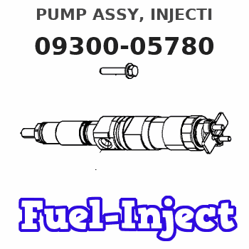
Information pump assy, injecti
Nozzle:
0935003820
Rating:
KIT List:
| Governor assy, mec | 1908900271 |
| Timer assy, automa | 0918030050 |
| Pump assy, fuel fe | 1922900060 |
| Body assy, injecti | 1904400320 |
Components :
| 001. | PUMP ASSY, INJECTI | 09300-05780 |
| 002. | GOVERNOR ASSY, MEC | 09130-06170 |
| 003. | LEVER SET | 09129-10190 |
| 004. | COVER ASSY, GOVERN | 09145-00881 |
| 005. | TIMER ASSY, AUTOMA | 09180-03500 |
| 006. | PUMP ASSY, FUEL FE | 09210-01551 |
| 007. | BODY ASSY, INJECTI | 19010-00350 |
Scheme ###:
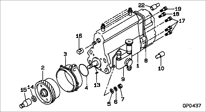
| 000. | [01] | 09300-05780 | PUMP ASSY, INJECTI | ME215005 |
| 001. | [01] | 19010-00350 | BODY ASSY, INJECTI | ME736204 |
| 002. | [01] | 09180-03500 | TIMER ASSY, AUTOMA | ME736210 |
| 003. | [01] | 09006-00450 | COVER SUB-ASSY, TI | ME736126 |
| 004. | [01] | 94914-02840 | O-RING | MH035502 |
| 005. | [04] | 94901-15020 | WASHER, STEEL PLAT | MH005068 |
| 006. | [04] | 90258-10001 | WASHER, SPRING | MC327716 |
| 007. | [04] | 91266-10081 | NUT, HEXAGON | MF430122 |
| 008. | [01] | 09130-06170 | GOVERNOR ASSY, MEC | ME743222 |
| 009. | [01] | 09210-01551 | PUMP ASSY, FUEL FE | ME703037 |
| 010. | [01] | 09028-50021 | CAP | ME035845 |
| 013. | [01] | 94913-00210 | KEY, WOODRUFF | ME702047 |
| 014. | [01] | 94901-40210 | WASHER, COUNTERSUN | ME702043 |
| 015. | [01] | 09001-20220 | NUT, TIMER ROUND | ME702033 |
| 016. | [01] | 09001-80090 | COVER, CONTROL RAC | ME702251 |
| 017. | [05] | 94904-72690 | BOLT, W/WASHER | ME702045 |
| 018. | [01] | 91418-06201 | BOLT, W/WASHER | ME702041 |
| 019. | [01] | 94904-73910 | BOLT, W/WASHER | ME703449 |
| 022. | [01] | 09028-50050 | CAP | ME076458 |
Include in #3:
09300-05780
as PUMP ASSY, INJECTI
Cross reference number
| Part num | Firm num | Firm | Name |
| 09300-05780 | ME215005 | PUMP ASSY, INJECTI | |
| ME215005 | MITSUBISHI | PUMP ASSY, INJECTI |
Information:
3. Make an adjustment of the legs on tool (A) for the length of the cylinder liner. Be careful not to damage the piston cooling tube at the bottom of the cylinder liner.4. Install tool (A) and remove the cylinder liner. 5. Remove filler band (2) and O-ring seals (1) from the cylinder liner.Install Cylinder Liners
1. Clean the cylinder liners and liner bores in the block.2. Install the liners in the block without seals or filler bands.3. Check the cylinder liner projection as follows: a) Install the 3/4"-16 NF bolts and 2F126 Washers of tooling (A) on the spacer plate around each cylinder liner as shown. Tighten the bolts evenly in four steps. 1. Tighten to a torque of 10 lb.ft. (14 N m).2. Tighten to a torque of 25 lb.ft. (35 N m).3. Tighten to a torque of 50 lb.ft. (70 N m).4. Tighten to a torque of 70 lb.ft. (95 N m).b) Put the adapter plate and one plate of tooling (A) on top of the liner and install the remainder of tooling (A). Be sure the crossbar is in position at the center of the liner. Tighten the bolts that hold tooling (A) evenly in four steps:1. Tighten to a torque of 5 lb.ft. (7 N m).2. Tighten to a torque of 15 lb.ft. (20 N m).3. Tighten to a torque of 25 lb.ft. (35 N m).4. Tighten to a torque of 50 lb.ft. (70 N m).c) Check to be sure the distance from the bottom edge of the bar to the top of the cylinder block is the same on both sides of the cylinder liner.d) Check the cylinder liner projection with tooling (B) at four locations around the cylinder liner. See the Specifications Section for the correct liner projection.
1. Clean the cylinder liners and liner bores in the block.2. Install the liners in the block without seals or filler bands.3. Check the cylinder liner projection as follows: a) Install the 3/4"-16 NF bolts and 2F126 Washers of tooling (A) on the spacer plate around each cylinder liner as shown. Tighten the bolts evenly in four steps. 1. Tighten to a torque of 10 lb.ft. (14 N m).2. Tighten to a torque of 25 lb.ft. (35 N m).3. Tighten to a torque of 50 lb.ft. (70 N m).4. Tighten to a torque of 70 lb.ft. (95 N m).b) Put the adapter plate and one plate of tooling (A) on top of the liner and install the remainder of tooling (A). Be sure the crossbar is in position at the center of the liner. Tighten the bolts that hold tooling (A) evenly in four steps:1. Tighten to a torque of 5 lb.ft. (7 N m).2. Tighten to a torque of 15 lb.ft. (20 N m).3. Tighten to a torque of 25 lb.ft. (35 N m).4. Tighten to a torque of 50 lb.ft. (70 N m).c) Check to be sure the distance from the bottom edge of the bar to the top of the cylinder block is the same on both sides of the cylinder liner.d) Check the cylinder liner projection with tooling (B) at four locations around the cylinder liner. See the Specifications Section for the correct liner projection.