Information pump assy, injecti
Nozzle:
0935004450
Rating:
KIT List:
| Body assy, injecti | 1904400320 |
| Governor assy, mec | 1908900271 |
| Timer assy, automa | No Application |
| Pump assy, fuel fe | 1922900060 |
Components :
| 001. | PUMP ASSY, INJECTI | 09300-04930 |
| 002. | BODY ASSY, INJECTI | 09010-09220 |
| 003. | GOVERNOR ASSY, MEC | 09130-04730 |
| 004. | COVER ASSY, GOVERN | 09145-00881 |
| 005. | COVER ASSY, GOVERN | 09145-00901 |
| 006. | TIMER ASSY, AUTOMA | 09180-02782 |
| 007. | PUMP ASSY, FUEL FE | 09210-01510 |
Scheme ###:
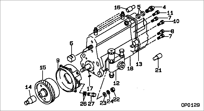
| 000. | [01] | 09300-04930 | PUMP ASSY, INJECTI | 22010-7290 |
| 000. | [01] | 09300-04930 | PUMP ASSY, INJECTI | S2201-07290 |
| 004. | [01] | 09031-00130 | VALVE ASSY, OVERFL | 22107-1090A |
| 005. | [02] | 94901-02480 | WASHER | 22847-1940A |
| 006. | [01] | 09001-80090 | COVER, CONTROL RAC | 22114-1250A |
| 007. | [04] | 94904-72690 | BOLT, W/WASHER | 22815-2410A |
| 008. | [01] | 94904-74850 | BOLT, W/WASHER | 22815-2900A |
| 009. | [01] | 09006-00410 | COVER SUB-ASSY, TI | 22501-1110A |
| 010. | [01] | 91418-06201 | BOLT, W/WASHER | 22815-1290A |
| 011. | [01] | 94904-73910 | BOLT, W/WASHER | 22815-2820A |
| 012. | [01] | 09210-01510 | PUMP ASSY, FUEL FE | 22570-1240A |
| 013. | [01] | 09130-04730 | GOVERNOR ASSY, MEC | |
| 014. | [01] | 09001-20220 | NUT, TIMER ROUND | 22511-1060A |
| 015. | [01] | 09180-02782 | TIMER ASSY, AUTOMA | 22510-2161 |
| 016. | [01] | 09028-50050 | CAP | 22323-1430A |
| 017. | [01] | 90458-04051 | KEY, WOODRUFF | 22895-1080A |
| 018. | [01] | 09010-09220 | BODY ASSY, INJECTI | 22110-2730A |
| 021. | [01] | 09028-50030 | CAP | 22323-1210A |
| 022. | [04] | 91266-10081 | NUT, HEXAGON | 22825-1490A |
| 023. | [04] | 94901-15020 | WASHER, STEEL PLAT | 22877-1551A |
| 024. | [04] | 90258-10001 | WASHER, SPRING | 28219-1120A |
| 026. | [02] | 94901-02500 | WASHER | 22847-1920A |
| 027. | [01] | 94918-00420 | SCREW, HOLLOW | 22835-1180A |
Include in #3:
09300-04930
as PUMP ASSY, INJECTI
09300-04930
Cross reference number
| Part num | Firm num | Firm | Name |
| 09300-04930 | 22010-7290 | PUMP ASSY, INJECTI | |
| 22010-7290 | HINO | PUMP ASSY, INJECTI | |
| S2201-07290 | HINO | PUMP ASSY, INJECTI |
Information:
Problem
Problems with startability and rough operation immediately following initial start up may occur on certain 3408 and 3412 Marine Engines. Also, these engines may experience a power loss due to high pressure leakage at the fuel injection pump bonnets.
Affected Product
Model & Identification Number
3408B (8RG1-120)
3412 (3JK1-60, 3JK63-75, 3JK77-81, 3JK83-176)
Parts Needed
8 - 7E4847 Seal (for 3408B, 12 for 3412)2 - 4F7957 Capscrew8 - 6I1665 Bonnet (for 3408B, 12 for 3412)2 - 3J7354 Seal-O-Ring2 - 5P0537 Washer2 - 5P2645 Elbow2 - 2V3216 Clip1 - 058593 Seal1 - 1083795 Cover-Oil Pump1 - 1083796 Cover-Bypass1 - 1083964 Line Assembly1 - 1084420 Gasket-Bypass CoverAction Required
See attached rework procedure.
Service Claim Allowances
This is a 6-hour job.
Parts Disposition
Handle the parts in accordance with your Warranty Bulletin on warranty parts handling.
Attach. (1-Rework Procedure)Rework Procedure
1. Remove the 9Y6037 Cover Assembly from the rear section of the fuel injection and governor group. Save the 2-1B2714, 2-1B2713, and 1-7B8167 Bolts.2. Remove the 9Y6036 Cover from the top of the 9Y6037 Cover Assembly to reveal the 4N0605 Spring and 4N1767 Valve. Clean and save the spring and valve in addition to the 1-0S1616 Bolt and 1-9F7022 Bolt for reuse.3. Install the spring and valve in the new 1083796 Cover Assembly. Install (dry) a new 1084420 Gasket. Use the 1-0S1616 Bolt and 1-9F7022 Bolt to assemble 1083796 Cover to the 1083795 Cover. See Illustration 1.
Illustration 14. Install the new assembly where the previous assembly was removed from the pump group reusing the bolts from Step 1. Use a new 0058593 Seal when installing the cover assembly onto the injection pump. See Illustration 2.5. Install a 3J7354 Seal onto each 5P2645 Elbow. Install an elbow into each threaded port in the cover assembly but do not tighten, yet.6. Remove the two existing 0S1615 Bolts from the fuel gallery cover as shown in Illustration 2. Install the 2-2V3216 Clips onto the 1083964 Line Assembly so they line up with the bolt holes on the fuel gallery cover.7. Install the 1083694 Line Assembly onto the two elbows. Install 2-4F7957 Bolts and 2-5P0537 Washers through the clips and into the pump housing.8. Tighten the elbows to the covers and tighten the line assembly nuts onto the elbows. Tighten the clip retaining bolts using standard bolt torque.
Illustration 29. Zero the injection pump racks and pin them in place. Remove the fuel injection lines from the pump bonnets.10. Remove 4P2899 Bushings and 4P7681 Pump Groups from the fuel injection pump. Identify the bushings and pump groups so that they can be installed in the same holes from which they were removed.11. Remove the existing 2W3409 Bonnets from the 4P7681 Pump Groups and install new 6I1665 Bonnets as shown in Illustration 3. If the barrel face of an individual injection pump is stained, the face may be lapped. Use 600 grit abrasive and lap the face on a flat surface in a figure 8 pattern. Lap the barrel face no more than 10 times in the figure 8 motion. If the stains still remain, replace the 7E6007 Plunger and Barrel