Information pump assy, injecti
Nozzle:
0935003820
Rating:
KIT List:
| Body assy, injecti | 1904400320 |
| Pump assy, fuel fe | 1922900060 |
| Governor assy, mec | 1908900170 |
Components :
| 001. | PUMP ASSY, INJECTI | 09300-04150 |
| 002. | BODY ASSY, INJECTI | 09010-09800 |
| 003. | PUMP ASSY, FUEL FE | 09210-01540 |
| 004. | GOVERNOR ASSY, MEC | 19080-02990 |
Scheme ###:
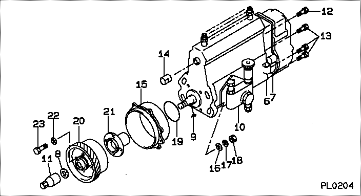
| 000. | [01] | 09300-04150 | PUMP ASSY, INJECTI | ME080585 |
| 006. | [01] | 09010-09800 | BODY ASSY, INJECTI | ME728935 |
| 007. | [01] | 19080-02990 | GOVERNOR ASSY, MEC | ME728238 |
| 008. | [01] | 94901-40210 | WASHER, COUNTERSUN | ME702043 |
| 009. | [01] | 94913-00210 | KEY, WOODRUFF | ME702047 |
| 010. | [01] | 09210-01540 | PUMP ASSY, FUEL FE | ME703397 |
| 011. | [01] | 09001-20220 | NUT, TIMER ROUND | ME702033 |
| 012. | [01] | 91518-08221 | BOLT, W/WASHER | MM500963 |
| 013. | [06] | 91418-06161 | BOLT, W/WASHER | ME702149 |
| 014. | [01] | 09001-80090 | COVER, CONTROL RAC | ME702251 |
| 015. | [01] | 09006-00320 | COVER SUB-ASSY, TI | ME703649 |
| 016. | [04] | 94901-15020 | WASHER, STEEL PLAT | MH005068 |
| 017. | [04] | 90258-10001 | WASHER, SPRING | MC327716 |
| 018. | [04] | 91266-10081 | NUT, HEXAGON | MF430122 |
| 019. | [01] | 94914-02840 | O-RING | MH035502 |
| 020. | [01] | 09185-10330 | GEAR, TIMER DRIVIN | ME728032 |
| 021. | [01] | 09255-10412 | BLOCK, COUPLING | ME017724 |
| 022. | [04] | 90258-08001 | WASHER, SPRING | MB239626 |
| 023. | [04] | 94904-04471 | BOLT, HEXAGON | ME702248 |
Include in #3:
09300-04150
as PUMP ASSY, INJECTI
Cross reference number
| Part num | Firm num | Firm | Name |
| 09300-04150 | ME080585 | PUMP ASSY, INJECTI | |
| ME080585 | MITSUBISHI | PUMP ASSY, INJECTI |
Information:
Introduction
This Special Instruction explains the calibration procedure for the heavy sleeve (commonly called the thick sleeve) metering fuel system. This Special Instruction shows:* The differences between the new 133-8985 Governor And Fuel Injection Pump Group, (HSMFS) and the 109-0324 Governor And Fuel Injection Pump Group, Sleeve Metering Fuel System (SMFS).* Calibration procedure for setting the 124-5932 Lever Assemblies.Recommended Tools
* 4C-9738 Torque Screwdriver set at 1.7 N m (15 lb in).* 4C-9738 Torque Screwdriver set at 4.0 N m (35 lb in).Required Tooling
* 3P-2200 Sleeve Setting Group: The HSMFS Injection Pump Group requires the use of many of the past 3208 Calibration Tools. A few new dedicated tools are required for the HSMFS.
Illustration 1. Parts included, and parts required but not included within the 3P-2200 Sleeve Setting Group. See Chart 1 and Chart 2 for item and part numbers. The 3P-2200 Sleeve Setting Group is used to set, test and adjust SMFS Injection Pump Groups.Reference, Special Instruction; SMHS6988, "Use Of 3P-2200 Calibration Tool Group".Special Instruction, SMHS7013, "Use Of The 5P-4203 Field Service Tool Group Or 5P-6577 Fuel Setting Tool Group". All tools may be stored in a 6V-3073 Plastic Case. The lid contains a 6V-4094 Liner and 6V-4873 Packing in the bottom for protection. The 6V-4873 Packing is topped with a 2P-8289 Tool Holder Block.
Illustration 2. The 5P-4203 Tool Group. See chart 3. for item and part number. 109-0324 Governor And Fuel Injection Pump Group (SMFS).
Illustration 3. View of the 109-0324 Governor And Fuel Injection Pump Group (SMFS). (1) 9N-5820 Lever. (2) 124-5941 Shaft. (3) 9Y-7791 Sleeve.The SMFS Injection Pump Group 9.0 mm (.35 in) 9Y-7791 Sleeve (3) has four 9N-5820 Levers (1) on each 124-5941 Shaft (2). The 9N-5820 Levers are indexed from the front. The 9Y-7791 Sleeve and 9N-5820 Lever indexes with the groove in the 9Y-7791 Sleeve.133-8985 Governor And Fuel Injection Pump Group (HSMFS).
Illustration 4. View of the HSMFS Injection Pump Group.
(1) 124-5932 Lever Assembly. (2) 124-5941 Shaft. (3) 124-5934 Sleeve.
Illustration 5. View of the HSMFS Injection Pump Group.
(1) 124-5932 Lever Assembly. (4) 126-7232 Dowel.The new 124-5934 Sleeve (3) is thicker than the former 9Y-7791 Sleeve (3). The new 124-5934 Sleeve can be operated at higher injection pressures needed for emissions control. As a result of its increased thickness, the 124-5934 Sleeve can not be indexed from the front. It must be indexed between two 124-5934 Sleeves.The new 124-5932 Lever Assembly (1) has a 126-7232 Dowel (4) that is split in half. The split 126-7232 Dowel is positioned between two 133-8984 Fuel Pump Assemblies and indexes two 124-5934 Sleeves (3) at the same time.
Illustration 6. Side view of one bank of the HSMFS Injection Pump Group. (1) 124-5932 Lever Assemblies. (2) 124-5941 Shaft.There are two 124-5932 Lever Assemblies (1) on the 124-5941 Shaft (2) of the HSMFS Injection Pump Group, instead of four 9N-5820 levers (1) on each 124-5941 Shaft (2) on the SMFS Injection Pump Group. Each 124-5932 Lever Assembly is positioned in between two and indexes two 133-8984 Fuel Pump Assemblies and two 124-5934