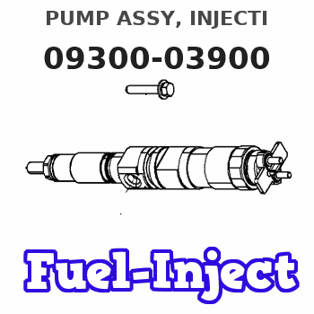
Information pump assy, injecti
Nozzle:
0935004450
Rating:
KIT List:
| Body assy, injecti | 1904400320 |
| Governor assy, mec | 1908900271 |
| Timer assy, automa | No Application |
| Pump assy, fuel fe | 1922900060 |
Components :
| 001. | PUMP ASSY, INJECTI | 09300-03900 |
| 002. | BODY ASSY, INJECTI | 09010-09230 |
| 003. | GOVERNOR ASSY, MEC | 09130-03072 |
| 004. | COVER ASSY, GOVERN | 09145-00361 |
| 005. | COVER ASSY, GOVERN | 09145-00881 |
| 006. | COVER ASSY, GOVERN | 09145-00901 |
| 007. | TIMER ASSY, AUTOMA | 09180-02782 |
| 008. | PUMP ASSY, FUEL FE | 09210-01510 |
Scheme ###:
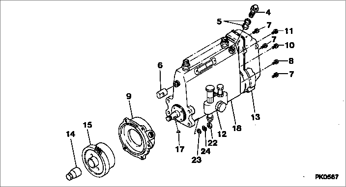
| 000. | [01] | 09300-03900 | PUMP ASSY, INJECTI | 22010-6440 |
| 000. | [01] | 09300-03900 | PUMP ASSY, INJECTI | S2201-06440 |
| 004. | [01] | 09031-00130 | VALVE ASSY, OVERFL | 22107-1090A |
| 005. | [02] | 94901-02480 | WASHER | 22847-1940A |
| 006. | [01] | 09001-80090 | COVER, CONTROL RAC | 22114-1250A |
| 007. | [04] | 94904-72690 | BOLT, W/WASHER | 22815-2410A |
| 008. | [01] | 94904-74850 | BOLT, W/WASHER | 22815-2900A |
| 009. | [01] | 09006-00350 | COVER SUB-ASSY, TI | 22501-1020B |
| 010. | [01] | 91418-06201 | BOLT, W/WASHER | 22815-1290A |
| 011. | [01] | 94904-73910 | BOLT, W/WASHER | 22815-2820A |
| 012. | [01] | 09210-01510 | PUMP ASSY, FUEL FE | 22570-1240A |
| 013. | [01] | 09130-03072 | GOVERNOR ASSY, MEC | 22310-4151B |
| 014. | [01] | 09001-20220 | NUT, TIMER ROUND | 22511-1060A |
| 015. | [01] | 09180-02782 | TIMER ASSY, AUTOMA | 22510-2161 |
| 017. | [01] | 90458-04051 | KEY, WOODRUFF | 22895-1080A |
| 018. | [01] | 09010-09230 | BODY ASSY, INJECTI | |
| 022. | [04] | 91266-10081 | NUT, HEXAGON | 22825-1490A |
| 023. | [04] | 94901-15020 | WASHER, STEEL PLAT | 22877-1551A |
| 024. | [04] | 90258-10001 | WASHER, SPRING | 28219-1120A |
Include in #3:
09300-03900
as PUMP ASSY, INJECTI
09300-03900
Cross reference number
| Part num | Firm num | Firm | Name |
| 09300-03900 | 22010-6440 | PUMP ASSY, INJECTI | |
| 22010-6440 | HINO | PUMP ASSY, INJECTI | |
| S2201-06440 | HINO | PUMP ASSY, INJECTI |
Information:
Caterpillar: Confidential Yellow
The information supplied in this service letter may not be valid after the termination date of this program. Do not perform the work outlined in this Service Letter after the termination date without first contacting your Caterpillar product analyst.
This Program can be administered either before or after a failure. In either case the decision whether to apply the Program is made by the dealer. When reporting the repair, use "PS4729" as the Part Number and "7755" as the Group Number. If administered before failure, use "56" as the Warranty Claim Description Code and use "T" as the SIMS Description Code. If administered after failure, use "96" as the Warranty Claim Description Code and use "Z" as the SIMS Description Code.
Termination Date
December 31, 1992Problem
The retainer clips for the fuel injectors may crack or break on certain Challenger 75 Tractors. Also, the unit injector rocker arms may crack.
Affected Product
Mode & Identification Number
CH75 (4CJ1-308, 4CJ311-317, 4CJ320-331, 4CJ350, 4CJ356,4CJ375-378, 4CJ380, 4CJ382, 4CJ383, 4CJ386, 4CJ391, 4CJ394, 4CJ396, 4CJ406)
Parts Needed
6 - 7E8872 Rocker Arm Assembly (Use as needed)6 - 6I2538 Clip6 - 0R3398 Injector Group (Use as needed)Action Required
See attached rework procedure.
Service Claim Allowances
If required, add the following:
0.5 Hr R&I first fuel injector0.4 Hr R&I each additional fuel injectorParts Disposition
Handle the parts in accordance with your Warranty Bulletin on warranty parts handling.
Attach.
(1-Rework Procedure)Rework Procedure
1. Check for 3X stamped on the block next to the serial number plate. If the block has been stamped do not proceed with the rework unless suspect injectors have recently been installed in that engine. Check SIMS history to be sure.2. Remove hood from over engine, valve covers, and rocker arm stands.3. Inspect the injector rocker arms for the heat code and die code as shown in Illustration 1. Replace any injector rocker arms that have both heat code "1" and die code "1*C" (* Note symbol in Illustration.)
Illustration 1 - Injector Rocker Arm Identification Injector rocker arms must have BOTH heat code "1" and die code "1*C" to be eligible for replacement.
4. Inspect unit injectors for a paint strip across the top face of the spring retainer (either yellow or red). A paint stripe indicates the unit injector has been reworked previously.5. Remove the return to tank fuel line at the fuel manifold adapter (siphon break) and install a 0-100 psi gauge at the manifold.6. Use an O-ring pick to remove the O-ring from the spring retainer of each injector to be reworked. Remove the rocker arm thrust pad from each injector.7. Pressurize fuel system using the priming pump to 30 psi and maintain pressure from 15-30 psi during rework (fuel pressure keeps the injector plunger extended during clip replacement).8. Inspect the 9U5300 Unit Injector Spring Compressor Group. See Illustration 2. The 9U5320 Fixture is for off engine use only.
Illustration 2 - 9U5300 Unit Injector Spring Compressor GroupInstall the compressor group into a rocker arm support bolt hole with the arm aligned over a unit injector spring. Be sure the 5P0541 Nut is backed off