Information pump assy, injecti
Nozzle:
0935001830
Rating:
KIT List:
| Body assy, injecti | 1904400300 |
| Timer assy, automa | 0918030050 |
| Pump assy, fuel fe | 1922900060 |
| Governor assy, mec | 1908900250 |
Components :
| 001. | PUMP ASSY, INJECTI | 09300-02100 |
| 002. | BODY ASSY, INJECTI | 09010-05421 |
| 003. | TIMER ASSY, AUTOMA | 09180-02240 |
| 004. | PUMP ASSY, FUEL FE | 09210-01140 |
| 005. | GOVERNOR ASSY, MEC | 19080-00601 |
| 005. | GOVERNOR ASSY, MEC | 19080-00601 |
| 005. | GOVERNOR ASSY, MEC | 19080-00601 |
Scheme ###:
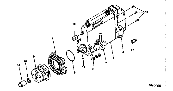
| 000. | [01] | 09300-02100 | PUMP ASSY, INJECTI | ME006206 |
| 003. | [01] | 09010-05421 | BODY ASSY, INJECTI | ME006161 |
| 004. | [01] | 19080-00601 | GOVERNOR ASSY, MEC | ME703374 |
| 005. | [01] | 09210-01140 | PUMP ASSY, FUEL FE | ME016021 |
| 006. | [01] | 09180-02240 | TIMER ASSY, AUTOMA | ME703026 |
| 007. | [01] | 09006-00140 | COVER SUB-ASSY, TI | ME006130 |
| 008. | [01] | 94914-03990 | O-RING | MH035501 |
| 009. | [04] | 94901-15020 | WASHER, STEEL PLAT | MH005068 |
| 012. | [01] | 94913-00190 | KEY, WOODRUFF | ME703361 |
| 013. | [01] | 94901-50500 | WASHER, SPRING | ME008373 |
| 014. | [01] | 09001-20260 | NUT, TIMER ROUND | ME703450 |
| 015. | [01] | 09001-80081 | COVER, CONTROL RAC | ME702034 |
| 016. | [06] | 94904-70620 | BOLT, W/WASHER | ME703359 |
| 020. | [02] | 09028-50021 | CAP | ME035845 |
Include in #3:
09300-02100
as PUMP ASSY, INJECTI
Cross reference number
| Part num | Firm num | Firm | Name |
| 09300-02100 | ME006206 | PUMP ASSY, INJECTI | |
| ME006206 | MITSUBISHI | PUMP ASSY, INJECTI |
Information:
Illustration 1 g00290899
ETR Junction Box with oil pressure protection (OP) and water temperature protection (WT) that does not require a switchgear for use on 3200 through 3400 Engines
(1) Terminal strips (TS)
(2) Wiring harness
(3) Junction box
(4) Identification foil
(5) Jumper between terminals (TS-3) and (TS-4)
(6) Jumper between terminals (TS-4) and (TS-5)
(7) Jumper between terminals (TS-5) and (TS-6)
(8) Emergency stop switch (ES)
(9) Jumper between terminals (TS-28) and (TS-29)
(10) Jumper between terminals (TS-30) and (TS-31)
(11) Slave relay (SR1)
(12) Slave relay (SR2) for air shutoff solenoid (ASOS)
(13) Grommets for engine oil pressure switches
(14) Start/stop switch (SSS)
(15) Slave relay (SR3) for starting aid switch (if equipped)
(16) Circuit breakers
(17) Mounting brackets for grommets
(18) Engine oil pressure switch (OPS1) Introduction
The ETR Junction Box with oil pressure protection (OP) and water temperature protection (WT) that does not require a switchgear is a system that has full protection. The system has a junction box arrangement that is designed to monitor four functions:
Oil pressure
Coolant temperatureThe junction box includes the following components:
Start/stop switch (SSS) (14)
Slave relay (SR1) (11)
Slave relay (SR2) (12)
Oil pressure switch (OPS1) (18)
Emergency stop switch (ES) (8)The components that are listed below operate with the junction box. The components are also mounted on the engine.
Fuel shutoff solenoid (FSOS)
Water temperature switch (WTS)The slave relay (SR1) must be energized in order for the engine to run with the ETR electric protection system.An air shutoff solenoid (ASOS) is not used because the engine overspeed is not monitored.Note: If the customer installs a mechanical overspeed switch on the engine, remove the jumper between terminals (TS-3) and (TS-4) on the terminal strip of the junction box.Electrical Schematics and Wiring Diagrams
This manual contains the point-to-point wiring diagrams for the complete electric protection system and the junction box. Four types of electrical schematics for each electric protection system arrangement are shown in this service manual.
Junction box wiring diagram
IEC (International Electro-Technical Commission) schematic
JIC (Joint Industrial Council) schematic
Junction box wiring harness diagramNote: The line number that follows a component code gives the location of the component on the IEC and JIC schematics.Circuit Operation With No Faults
Engine Shutdown
When the engine is stopped, power is not available to any of the protection components. All switches are then in the normally open position or the normally closed position.Engine Start-up
Illustration 2 g00282739
5N-0364 Switch
(1) Keyway
Table 1
Switch Position Contacts that are closed
START (A) 1-2 and 4-5
RUN (B) 2-3 and 4-5
STOP (C) 2-3 and 5-6 A toggle switch is located on the front of the junction box. The switch is spring loaded and the toggle switch is automatically returned to the RUN. This happens when the toggle is manually released from the START position. This start/stop switch (SSS) has three positions:
START (A)
RUN (B)
STOP (C)When the start/stop switch (SSS) is moved to the START position, the following events should occur in the electric circuit.
The start/stop switch (SSS) closes the circuit to the starting motor.
The starter motor magnetic switch (SMMS) (line 9) closes a contact (line 3) which energizes the pinion solenoid (PS) (line 3).
The PS closes a contact (line 2) which energizes the starter motor (SM).
The current