Information pump assy, injecti
Rating:
Components :
| 001. | PUMP ASSY, INJECTI | 09300-02094 |
| 002. | SWITCH KIT, CONTRO | 09009-90440 |
| 003. | BODY ASSY, INJECTI | 09010-06931 |
| 004. | GOVERNOR ASSY, MEC | 09130-01444 |
| 004. | GOVERNOR ASSY, MEC | 09130-01444 |
| 004. | GOVERNOR ASSY, MEC | 09130-01444 |
| 004. | GOVERNOR ASSY, MEC | 09130-01444 |
| 004. | GOVERNOR ASSY, MEC | 09130-01444 |
| 005. | COVER ASSY, GOVERN | 09145-00230 |
| 006. | COVER ASSY, GOVERN | 09145-00881 |
| 007. | TIMER ASSY, AUTOMA | 09180-02210 |
| 008. | PUMP ASSY, FUEL FE | 09210-01140 |
| 009. | PUMP ASSY, FUEL FE | 09210-01551 |
Scheme ###:
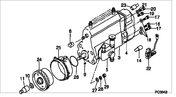
| 000. | [01] | 09300-02094 | PUMP ASSY, INJECTI | ME016299 |
| 003. | [01] | 09010-06931 | BODY ASSY, INJECTI | ME703258 |
| 004. | [01] | 09130-01444 | GOVERNOR ASSY, MEC | ME703036 |
| 005. | [01] | 09210-01140 | PUMP ASSY, FUEL FE | ME016021 |
| 005. | [01] | 09210-01551 | PUMP ASSY, FUEL FE | ME703037 |
| 006. | [01] | 09001-80090 | COVER, CONTROL RAC | ME702251 |
| 009. | [01] | 94913-00210 | KEY, WOODRUFF | ME702047 |
| 010. | [01] | 94901-40210 | WASHER, COUNTERSUN | ME702043 |
| 011. | [01] | 09001-20220 | NUT, TIMER ROUND | ME702033 |
| 014. | [01] | 09028-50021 | CAP | ME035845 |
| 016. | [01] | 09152-40280 | SCREW, STOPPER | |
| 016. | [01] | 94904-72990 | BOLT, W/WASHER | ME703038 |
| 016. | [01] | 94904-74850 | BOLT, W/WASHER | ME703933 |
| 017. | [03] | 94904-72690 | BOLT, W/WASHER | ME702045 |
| 017. | [04] | 94904-72690 | BOLT, W/WASHER | ME702045 |
| 018. | [01] | 90258-06001 | WASHER, SPRING | ME702596 |
| 019. | [02] | 91418-06201 | BOLT, W/WASHER | ME702041 |
| 019. | [01] | 91418-06201 | BOLT, W/WASHER | ME702041 |
| 020. | [01] | 94904-04300 | BOLT, HEXAGON | ME702044 |
| 020. | [01] | 94904-73910 | BOLT, W/WASHER | ME703449 |
| 021. | [01] | 90258-08001 | WASHER, SPRING | MB239626 |
| 022. | [01] | 09009-90440 | SWITCH KIT, CONTRO | ME016027 |
| 023. | [01] | 09028-50050 | CAP | ME076458 |
| 024. | [01] | 09180-02210 | TIMER ASSY, AUTOMA | ME703035 |
| 025. | [01] | 09006-00171 | COVER SUB-ASSY, TI | ME016071 |
| 025. | [01] | 09006-00320 | COVER SUB-ASSY, TI | ME703649 |
| 026. | [01] | 94914-02840 | O-RING | MH035502 |
| 027. | [04] | 94901-15020 | WASHER, STEEL PLAT | MH005068 |
| 028. | [04] | 90258-10001 | WASHER, SPRING | MC327716 |
| 029. | [04] | 91266-10081 | NUT, HEXAGON | MF430122 |
Include in #3:
09300-02094
as PUMP ASSY, INJECTI
Cross reference number
| Part num | Firm num | Firm | Name |
| 09300-02094 | ME016299 | PUMP ASSY, INJECTI |
Information:
Illustration 1 g00569647
ETR Junction Box with oil pressure protection (OP), water temperature protection (WT), and overspeed protection (OS) that does not require a switchgear for use on 3200 through 3400 Engines
(1) Terminal strips (TS)
(2) Wiring harness
(3) Electronic speed switch (ESS)
(4) Junction box
(5) Identification foil
(6) Jumper between terminals (TS-3) and (TS-4)
(7) Diodes (D3) and (D4)
(8) Emergency stop switch (ES)
(9) Jumper between terminals (TS-28) and (TS-29)
(10) Jumper between terminals (TS-30) and (TS-31)
(11) Slave relay (SR1)
(12) Slave relay (SR2) for air shutoff solenoid (ASOS)
(13) Grommets for engine oil pressure switches
(14) Start/stop switch (SSS)
(15) Circuit breakers
(16) Engine oil pressure switch (OPS1)
(17) Mounting brackets for grommets
Illustration 2 g00290419
ETR Junction Box with oil pressure protection (OP), water temperature protection (WT), and overspeed protection (OS) that does not require a switchgear for use on 3500 Engines
(1) Terminal strips (TS)
(2) Wiring harness
(3) Electronic speed switch (ESS)
(4) Junction box
(5) Identification foil
(6) Jumper between terminals (TS-3) and (TS-4)
(7) Diodes (D3) and (D4)
(8) Emergency stop switch (ES)
(9) Jumper between terminals (TS-27) and (TS-28)
(10) Jumper between terminals (TS-28) and (TS-29)
(11) Jumper between terminals (TS-30) and (TS-31)
(12) Diode for electric governor actuator (if equipped)
(13) Slave relay (SR1)
(14) Slave relay (SR2) for air shutoff solenoid (ASOS)
(15) Slave relay (SR3) for starting aid switch (if equipped)
(16) Grommets for engine oil pressure switches
(17) Start/stop switch (SSS)
(18) Circuit breakers
(19) Engine oil pressure switch (OPS1)
(20) Mounting brackets for grommets
(21) Engine oil pressure switch (OPS2) (if equipped) Introduction
The ETR Junction Box with oil pressure protection (OP), water temperature protection (WT), and overspeed protection (OS) that does not require a switchgear is a system that has full protection. The system has a junction box arrangement that is designed to monitor four functions:
Engine overspeed
Crank termination
Oil pressure
Coolant temperatureThe junction box includes the following components:
Electronic speed switch (ESS) (3)
Start/stop switch (SSS) (17) and (14)
Slave relay (SR1) (11) and (13)
Slave relay (SR2) (if equipped) with an air shutoff solenoid (ASOS) (12) and (14)
Oil pressure switch (OPS1) (16) and (19)
Oil pressure switch (OPS2) that is only in 3500 Engines (21)
Emergency stop switch (ES) (8)The components that are listed below operate with the junction box. The components are also mounted on the engine.
Fuel shutoff solenoid (FSOS)
Air shutoff solenoid (ASOS)
Water temperature switch (WTS)The slave relay (SR1) must be energized in order for the engine to run with the ETR electric protection system.Electrical Schematics and Wiring Diagrams
This manual contains the point-to-point wiring diagrams for the complete electric protection system and the junction box. Four types of electrical schematics for each electric protection system arrangement are shown in this service manual.
Junction box wiring diagram
IEC (International Electro-Technical Commission) schematic
JIC (Joint Industrial Council) schematic
Junction box wiring harness diagramNote: The line number that follows a component code gives the location of the component on the IEC and JIC schematics.Circuit Operation With No Faults
Engine Shutdown
When the engine is stopped, power is always available across the terminals (ESS-5) and (ESS-6) (line 54) of the electronic speed switch (ESS). All of the switches are in the normally open position or the normally closed positions at that time.Engine Start-up
Illustration 3 g00282721
2W-6832 Switch
(1) Keyway.
Table 1
Switch Position Contacts that