Information pump assy, injecti

Rating:
Components :
| 001. | PUMP ASSY, INJECTI | 09300-01972 |
| 002. | BODY ASSY, INJECTI | 09010-06192 |
| 003. | GOVERNOR ASSY, MEC | 09130-01761 |
| 004. | COVER ASSY, GOVERN | 09145-00360 |
| 005. | COVER ASSY, GOVERN | 09145-00881 |
| 006. | COVER ASSY, GOVERN | 09145-00901 |
| 007. | TIMER ASSY, AUTOMA | 09180-02310 |
| 008. | PUMP ASSY, FUEL FE | 09210-01510 |
Scheme ###:
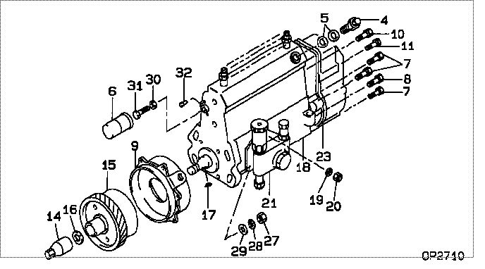
| 000. | [01] | 09300-01972 | PUMP ASSY, INJECTI | 22010-4760 |
| 004. | [01] | 09031-00130 | VALVE ASSY, OVERFL | 22107-1090A |
| 005. | [02] | 94901-02480 | WASHER | 22847-1940A |
| 006. | [01] | 09001-80401 | COVER, CONTROL RAC | 22114-1160A |
| 007. | [04] | 94904-72690 | BOLT, W/WASHER | 22815-2410A |
| 008. | [01] | 94904-74850 | BOLT, W/WASHER | 22815-2900A |
| 009. | [01] | 09006-00150 | COVER SUB-ASSY, TI | 22825-1470A |
| 010. | [01] | 91418-06201 | BOLT, W/WASHER | 22815-1290A |
| 011. | [01] | 94904-73910 | BOLT, W/WASHER | 22815-2820A |
| 014. | [01] | 09001-20220 | NUT, TIMER ROUND | 22511-1060A |
| 015. | [01] | 09180-02310 | TIMER ASSY, AUTOMA | 22510-1910A |
| 016. | [01] | 94901-40210 | WASHER, COUNTERSUN | 22867-1320A |
| 017. | [01] | 90458-04051 | KEY, WOODRUFF | 22895-1080A |
| 018. | [01] | 09010-06192 | BODY ASSY, INJECTI | 22110-2810A |
| 019. | [03] | 90258-06001 | WASHER, SPRING | 28219-1110A |
| 020. | [03] | 90160-06051 | NUT, HEXAGON | 22825-1480A |
| 021. | [01] | 09210-01510 | PUMP ASSY, FUEL FE | 22570-1240A |
| 023. | [01] | 09130-01761 | GOVERNOR ASSY, MEC | |
| 027. | [04] | 91266-10081 | NUT, HEXAGON | 22825-1490A |
| 028. | [04] | 90258-10001 | WASHER, SPRING | 28219-1120A |
| 029. | [04] | 94901-15020 | WASHER, STEEL PLAT | 22877-1551A |
| 030. | [01] | 90170-06361 | NUT, HEXAGON | 92100-6040A |
| 031. | [01] | 09003-10070 | SCREW, CONTROL RAC | 22396-1210A |
| 032. | [02] | 09045-90030 | PIN | 22358-1010A |
Include in #3:
09300-01972
as PUMP ASSY, INJECTI
Cross reference number
| Part num | Firm num | Firm | Name |
| 09300-01972 | 22010-4760 | PUMP ASSY, INJECTI |
Information:
Illustration 1 g00565418
4W-8471 Time Delay Relay
Use a 6V-7070 Digital Multimeter, a stopwatch, and a battery (8 volts to 40 volts) for this test.
Connect the positive lead of the voltage source to terminal (TD-4) of the time delay relay. Connect the negative lead to terminal (TD-3). If the test is done on an engine, the start/stop switch must be in the STOP position in order to power terminal (TD-6). All connections must be maintained until the tests are completed.
Use the multimeter to determine continuity. Compare the measurements to the following table.
Table 1
Terminals Relay Position
5-6 Closed
6-7 Open
Connect the positive lead of the voltage source to terminal (TD-1). If the time delay relay is tested on the engine do not leave the voltage source hooked to terminal (TD-1) for more than 60 seconds. The fuel shutoff solenoid will be energized. Use the multimeter to determine continuity. Compare the measurements to the following table.
Table 2
Terminals Relay Position
5-6 Open
6-7 Closed
Remove the positive lead of the voltage source from terminal (TD-1). Use the stopwatch to measure the time that is needed for the position of the relay to change. Use the multimeter to determine continuity. Compare the measurements to the following table.
Table 3
Terminals Delay Time of Relay Position
0 to 60 seconds 80 seconds or more
5-6 Open Closed
6-7 Closed Open Note: If a jumper is normally installed across terminals (TD-2) and (TD-3), the jumper must be removed before performing Step 5.
Connect the positive lead of the voltage source to terminal (TD-2). If the time delay relay is tested on the engine, do not leave the voltage source on terminal (TD-2) for more than 60 seconds. The fuel shutoff solenoid will be energized. Use the stopwatch to measure the time that is needed for the position of the relay to change. Use the multimeter to determine continuity. Compare the measurements to the following table.
Table 4
Terminals Delay Time of Relay Position
0 to 8 seconds 10 seconds or more
5-6 Closed Open
6-7 Open Closed
Remove the positive lead of the voltage source from terminal (TD-1). Use the stopwatch to measure the time that is needed for the position of the relay to change. Use the multimeter to determine continuity. Compare the measurements to the following table.
Table 5
Terminals Delay Time of Relay Position
0 to 60 seconds 80 seconds or more
5-6 Open Closed
6-7 Closed Open
Remove the voltage source from terminal (TD-4). Use the multimeter to determine continuity. Compare the measurements to the following table.
Table 6
Terminals Relay Position
5-6 Closed
6-7 Open