Information pump assy, injecti
Nozzle:
0935001320
Rating:
KIT List:
| Body assy, injecti | 1904400300 |
| Governor assy, mec | 1908900170 |
| Timer assy, automa | 0918030050 |
| Pump assy, fuel fe | 1922900060 |
Components :
| 001. | PUMP ASSY, INJECTI | 09300-01710 |
| 002. | BODY ASSY, INJECTI | 09010-02922 |
| 003. | GOVERNOR ASSY, MEC | 09080-09760 |
| 004. | TIMER ASSY, AUTOMA | 09180-02330 |
| 005. | PUMP ASSY, FUEL FE | 09210-01540 |
Scheme ###:
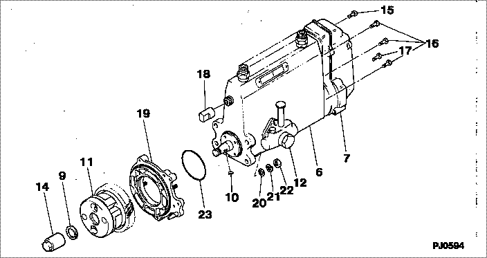
| 000. | [01] | 09300-01710 | PUMP ASSY, INJECTI | ME008363 |
| 006. | [01] | 09010-02922 | BODY ASSY, INJECTI | ME703495 |
| 007. | [01] | 09080-09760 | GOVERNOR ASSY, MEC | ME703950 |
| 009. | [01] | 94901-50500 | WASHER, SPRING | ME008373 |
| 010. | [01] | 94913-00190 | KEY, WOODRUFF | ME703361 |
| 011. | [01] | 09180-02330 | TIMER ASSY, AUTOMA | ME703497 |
| 012. | [01] | 09210-01540 | PUMP ASSY, FUEL FE | ME703397 |
| 014. | [01] | 09001-20080 | NUT, TIMER ROUND | ME022426 |
| 014. | [01] | 09001-20260 | NUT, TIMER ROUND | ME703450 |
| 015. | [01] | 91518-08221 | BOLT, W/WASHER | MM500963 |
| 016. | [05] | 91418-06161 | BOLT, W/WASHER | ME702149 |
| 017. | [01] | 91518-06121 | BOLT, W/WASHER | ME703399 |
| 018. | [01] | 09001-80081 | COVER, CONTROL RAC | ME702034 |
| 019. | [01] | 09006-00140 | COVER SUB-ASSY, TI | ME006130 |
| 020. | [04] | 94901-15020 | WASHER, STEEL PLAT | MH005068 |
| 021. | [04] | 90258-10001 | WASHER, SPRING | MC843842 |
| 022. | [04] | 91266-10081 | NUT, HEXAGON | MF430122 |
| 023. | [01] | 94914-03990 | O-RING | MH035501 |
Include in #3:
09300-01710
as PUMP ASSY, INJECTI
Cross reference number
| Part num | Firm num | Firm | Name |
| 09300-01710 | ME008363 | PUMP ASSY, INJECTI | |
| ME008363 | MITSUBISHI | PUMP ASSY, INJECTI |
Information:
Introduction
This Special Instruction gives detailed instructions on the disassembly and assembly of the 144-0835 Unit Injector Hydraulic Pump . The 144-0835 Unit Injector Hydraulic Pump was not previously serviceable. The pump will have a kit that will contain serviceable parts. The rear bearing and the bearing kits for the pump will be serviceable on an individual basis.Note: This instruction should also be used when you are servicing the former 134-9405 Unit Injector Hydraulic Pump .Serviceable Parts
154-6732 Fuel Injection Pump Kit
Control Piston
Shaft
Yoke
Seal Kit
Front Bearing
Rotating Group
154-6734 Bearing
154-6735 Bearing Kit Required Tools
Contact the Caterpillar Dealer for the dimensions and specifications that are needed in order to fabricate the tools.
Illustration 1 g00295533
FT-2606 Yoke Fixture
Illustration 2 g00295534
Two FT-2607 Bearing Installation Tools
Illustration 3 g00295535
FT-2608 Bearing Installation Tool
Illustration 4 g00295536
FT-2609 Valve Block Positioner
Illustration 5 g00295537
FT-2610 Driver Tube
Illustration 6 g00295538
FT-2611 Bearing Support
Illustration 7 g00295539
FT-2612 Bearing Removal Tool Disassembly Of The 144-0835 Unit Injector Hydraulic Pump
Start by removing the 128-3552 Unit Injection Hydraulic Pump and Mounting Gp from the engine.Reference: Consult the Service Manual, SENR1063 for additional information.Note: Do not disconnect the fuel transfer pump from the 128-3552 Unit Injection Hydraulic Pump and Mounting Gp before servicing. The coupling between the two pumps will be used later.
Illustration 8 g00295292
(1) Fuel Transfer Pump. (2) Bolts.
Remove the four bolts (2) from the fuel transfer pump (1). Remove the fuel transfer pump (1) .
Illustration 9 g00295294
(3) Compensator. (4) Bolt.
Remove the four bolts (4) from the compensator (3). Remove the compensator (3) and the adapter. Do not adjust the compensator (3) .
Illustration 10 g00295295