Information pump assy, injecti
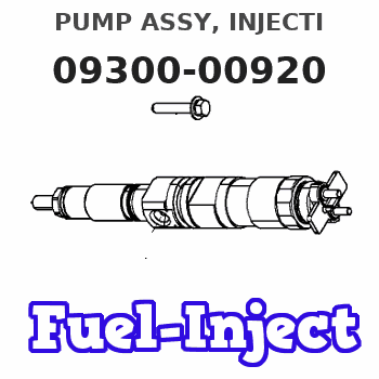
PUMP ASSY, INJECTI
DA
- *1 IF THE GOVERNOR PARTS 090573-0150X2,090721-0150,
- 091159-0500,091403-0460 ARE CHANGED AT THE SAME TIME,
- NEW BODY CAN BE USED FOR OLD PUMP. *2 IF THE BODY PART
- 090212-0441 IS CHANGED AT THE SAME TIME, NEW GOVERNOR
- CAN BE USED FOR OLD PUMP.
Nozzle:
0935002540
Rating:
KIT List:
| Body assy, injecti | 1904400320 |
| Governor assy, mec | 1908900271 |
| Timer assy, automa | 0918030050 |
| Pump assy, fuel fe | 1922900060 |
Cross reference number
| Part num | Firm num | Firm | Name |
| 09300-00920 | PUMP ASSY, INJECTI | ||
| 22010-3862 | HINO | PUMP ASSY, INJECTI |
Information:
Introduction
Do not perform any procedure in this Special Instruction until you have read the information and you understand the information.Safety Section
Do not operate or work on this product unless you have read and understood the instruction and warnings in the relevant Operation and Maintenance Manuals and relevant service literature. Failure to follow the instructions or heed the warnings could result in injury or death. Proper care is your responsibility.
Failure to follow all safety guidelines prescribed in this document and by governing authorities and regulatory agencies may result in severe injury or death of personnel or machine damage.
When removing a major component or attachment, ensure that it is properly blocked or secured before removing mounting hardware. An assembly that is disconnected without proper blocking may shift or fall, resulting in serious injury or death of personnel or machine damage.
Personal injury or death can result from improper maintenance procedures. To avoid injury or death, follow the procedures exactly as stated below.
Personal injury can result from improper handling of chemicals.Make sure you use all the necessary protective equipment required to do the job.Make sure that you read and understand all directions and hazards described on the labels and material safety data sheet of any chemical that is used.Observe all safety precautions recommended by the chemical manufacturer for handling, storage, and disposal of chemicals.
Climbing equipment may be required to access this service point. Refer to the Operation and Maintenance Manual, "Mounting and Dismounting" topic for safety information.
Before servicing/performing maintenance on the machine, electrical power must be physically disconnected; battery plugs must be disconnected from the batteries, or the trailing cable must be unplugged, and warning tags and padlocks shall be applied by a certified electrician. Certified electricians shall perform or direct any electrical work, including any energized testing, repair work in controllers, motors, or other approved compartments, and shall insure that all compartments are properly closed and inspected prior to re-energization. All applicable lock out and tag out procedures must be followed.
Do not operate the machine if any guards or covers are missing or inadequately secured. Personnel could be seriously injured or machine damage may occur.
Observe the safe working load limits of all lifting and blocking devices and keep a safe distance from suspended/blocked loads. Personnel may be seriously injured or killed by falling loads.
New Water Injection Check Valve for MD6250 Rotary Drills
Location
Illustration 1 g06400691
Location of 504-4521 Water Lines Gp and new check valve.
Note: Some parts are removed/hidden for clarity.Required Parts
Table 1
Required Parts
Item Qty New Part Number Part Name
1 1 3B-7255 Reducer Bushing
2 1 3J-1907 O-Ring Seal
3 1 235-3567 Adapter
4 1 573-4099 Check Valve
5 1 8C-6872 Connector
6 1 180-8424 O-Ring Seal Rework Procedure
Follow the below set of procedures to install the water side check valve in 504-4521 Water Lines Gp.Show/hide