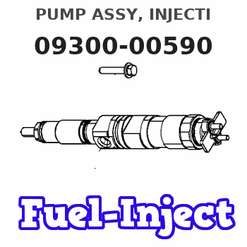
Information pump assy, injecti
Nozzle:
0935002390
Rating:
KIT List:
| Body assy, injecti | 1904400320 |
| Governor assy, mec | 1908900170 |
| Pump assy, fuel fe | 1922900060 |
Components :
| 001. | PUMP ASSY, INJECTI | 09300-00590 |
| 002. | BODY ASSY, INJECTI | 09010-05280 |
| 003. | GOVERNOR ASSY, MEC | 09080-08190 |
| 004. | PUMP ASSY, FUEL FE | 09210-01540 |
Scheme ###:
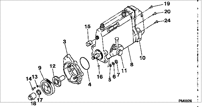
| 000. | [01] | 09300-00590 | PUMP ASSY, INJECTI | ME019628 |
| 003. | [01] | 09006-00171 | COVER SUB-ASSY, TI | ME016071 |
| 003. | [01] | 09006-00320 | COVER SUB-ASSY, TI | ME703649 |
| 004. | [01] | 94914-02840 | O-RING | MH035502 |
| 005. | [04] | 94901-15020 | WASHER, STEEL PLAT | MH005068 |
| 006. | [04] | 90258-10001 | WASHER, SPRING | MC327716 |
| 007. | [04] | 91266-10081 | NUT, HEXAGON | MF430122 |
| 008. | [01] | 09010-05280 | BODY ASSY, INJECTI | ME728057 |
| 009. | [01] | 09185-10310 | GEAR, TIMER DRIVIN | |
| 010. | [01] | 09080-08190 | GOVERNOR ASSY, MEC | ME017722 |
| 011. | [01] | 09210-01540 | PUMP ASSY, FUEL FE | ME703397 |
| 012. | [01] | 09255-10412 | BLOCK, COUPLING | ME017724 |
| 013. | [04] | 90258-08001 | WASHER, SPRING | MB239626 |
| 014. | [04] | 94904-04471 | BOLT, HEXAGON | ME702248 |
| 015. | [01] | 09001-80090 | COVER, CONTROL RAC | ME702251 |
| 016. | [01] | 94913-00210 | KEY, WOODRUFF | ME702047 |
| 017. | [01] | 94901-40210 | WASHER, COUNTERSUN | ME702043 |
| 018. | [01] | 09001-20220 | NUT, TIMER ROUND | ME702033 |
| 019. | [01] | 91518-08221 | BOLT, W/WASHER | MM500963 |
| 020. | [05] | 91418-06161 | BOLT, W/WASHER | ME702149 |
| 024. | [01] | 91518-06121 | BOLT, W/WASHER | ME703399 |
Include in #3:
09300-00590
as PUMP ASSY, INJECTI
Cross reference number
| Part num | Firm num | Firm | Name |
| 09300-00590 | ME019628 | PUMP ASSY, INJECTI | |
| ME019628 | MITSUBISHI | PUMP ASSY, INJECTI |
Information:
start by:a) remove fuel injection pump housing and governor 1. Install the fuel injection pump housing on tool (A).2. Remove the bolts (1) that hold the governor housing (2) to the fuel injection pump housing.3. Remove the governor housing (2). 4. Remove two springs (4) and the seat (5) from the governor housing.5. Remove the seat (7) from the shaft.6. Remove the spring (6) from the shaft.7. Remove the cover (3) from the pump housing. 8. Remove the shaft (8) and the lever (9) from the pump housing. 9. Remove the thrust collar (11) from the shaft.10. Remove the cover (10) from the pump housing. 11. Loosen the two bolts (13) that hold the torque spring assembly (12) and remove it from the pump housing. 12. Remove the pin (15) from the pump housing.13. Remove the screw (14) and the nut (16) from the pump housing.14. Remove the ring that holds the lever and remove the lever (18) from the dowel (17).15. Remove the dowel (17) from the pump housing. Dowel does not need to be removed unless camshaft is to be removed.
Pull on the shield only a small amount in each location so it will not have distortion or damage. A damaged shield must be replaced.
16. Remove the shield (19) from the camshaft with tool (B). 17. Install the timing pin (C) to hold the camshaft.18. Remove the bolts (20) that hold the flyweight assembly to the camshaft. 19. Remove the flyweight assembly (21) from the camshaft.20. Remove the timing pin (C) from the pump housing.Connection Of Governor To Fuel Injection Pump Housing
1. Put the fuel injection pump housing on the bracket assembly (A).2. Install the timing pin (B) to hold the camshaft.3. Put the flyweight assembly (1) in position on the camshaft. Be sure the pin that holds the shaft (2) is in position on the back of the flyweight assembly.4. Install the bolts that hold the flyweight assembly to the camshaft and tighten to a torque of 10 2 lb. ft. (1.38 0.28 mkg).5. Remove the timing pin (B). 6. Put the shield (3) in position over the flyweights. 7. Use the driver (C) to install the shield the remainder of the way on to the camshaft. 8. Put a new O-ring seal on the dowel (4) and install the dowel in the pump housing. Make the dowel even with the machined surface of the counterbore on the outside of the housing. 9. Put the lever (8) on the dowel (4) and install the ring that holds it on the dowel.10. Install the screw (6) and the nut (7) in the pump housing.11. Install the pin (5) in the pump housing. 12. Put the torque spring assembly (10) in position on the housing and tighten the two bolts (11) that hold it to the housing.13. Install the cover (9) on the pump housing. 14. Put the thrust collar (13) in position between the flyweights. Lift the flyweights up with a piece of wire