Information pump assy, injecti
Nozzle:
0935002390
Rating:
KIT List:
| Body assy, injecti | 1904400320 |
| Governor assy, mec | 1908900271 |
| Timer assy, automa | 0918030050 |
| Pump assy, fuel fe | 1922900060 |
| Pump assy, fuel fe | 1922900060 |
Components :
| 001. | PUMP ASSY, INJECTI | 09300-00550 |
| 002. | SWITCH KIT, CONTRO | 09009-90440 |
| 003. | BODY ASSY, INJECTI | 09010-05360 |
| 004. | GOVERNOR ASSY, MEC | 09130-00630 |
| 005. | COVER ASSY, GOVERN | 09145-00230 |
| 006. | TIMER ASSY, AUTOMA | 09180-01650 |
| 006. | TIMER ASSY, AUTOMA | 09180-01650 |
| 007. | PUMP ASSY, FUEL FE | 09210-01140 |
| 008. | PUMP ASSY, FUEL FE | 09210-01551 |
Scheme ###:
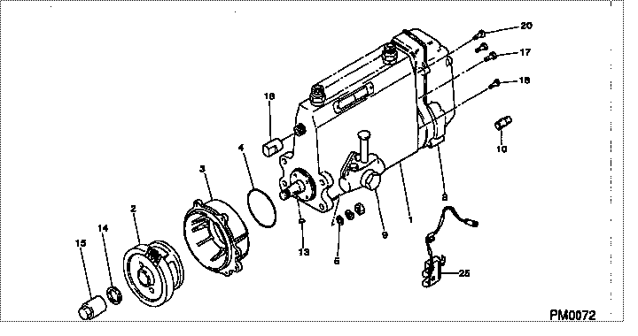
| 000. | [01] | 09300-00550 | PUMP ASSY, INJECTI | ME016094 |
| 001. | [01] | 09010-05360 | BODY ASSY, INJECTI | |
| 002. | [01] | 09180-01650 | TIMER ASSY, AUTOMA | ME016121 |
| 002. | [01] | 09180-01651 | TIMER ASSY, AUTOMA | ME016121 |
| 003. | [01] | 09006-00320 | COVER SUB-ASSY, TI | ME703649 |
| 003. | [01] | 09006-00171 | COVER SUB-ASSY, TI | ME016071 |
| 004. | [01] | 94914-02840 | O-RING | MH035502 |
| 005. | [04] | 94901-15020 | WASHER, STEEL PLAT | MH005068 |
| 008. | [01] | 09130-00630 | GOVERNOR ASSY, MEC | ME016147 |
| 009. | [01] | 09210-01551 | PUMP ASSY, FUEL FE | ME703037 |
| 009. | [01] | 09210-01140 | PUMP ASSY, FUEL FE | ME016021 |
| 010. | [01] | 09028-50021 | CAP | ME035845 |
| 013. | [01] | 94913-00210 | KEY, WOODRUFF | ME702047 |
| 014. | [01] | 94901-40210 | WASHER, COUNTERSUN | ME702043 |
| 015. | [01] | 09001-20220 | NUT, TIMER ROUND | ME702033 |
| 016. | [01] | 09001-80090 | COVER, CONTROL RAC | ME702251 |
| 016. | [01] | 09001-80120 | COVER, CONTROL RAC | ME702604 |
| 017. | [01] | 94904-72990 | BOLT, W/WASHER | ME703038 |
| 018. | [04] | 94904-72690 | BOLT, W/WASHER | ME702045 |
| 020. | [01] | 94904-73910 | BOLT, W/WASHER | ME703449 |
| 025. | [01] | 09009-90440 | SWITCH KIT, CONTRO | ME016027 |
Include in #3:
09300-00550
as PUMP ASSY, INJECTI
Cross reference number
| Part num | Firm num | Firm | Name |
| 09300-00550 | ME016094 | PUMP ASSY, INJECTI | |
| ME016094 | MITSUBISHI | PUMP ASSY, INJECTI |
Information:
Start By:a. remove oil pump 1. Check each main bearing cap (2) for its location on the engine. Each cap has an arrow (1) which shows the direction of the front of the block and a number (3) which gives the location of that cap.2. Remove No. 2 through No. 6 main bearing caps from the engine. Remove the lower bearings from the caps.3. Remove the thrust plate from each side of the No. 4 upper main bearing. 4. Turn the crankshaft until Tool (A) can be installed in oil hole (4). Turn the crankshaft in the direction which will push the upper main bearing out, tab end first.
If the crankshaft is turned in the wrong direction, the tab of the bearing will be pushed between the crankshaft and the cylinder block. This will cause damage to the crankshaft and block.
Install the main bearings dry when clearance checks are made. Put clean engine oil on the main bearings for final assembly. 5. Install lower bearings in the bearing caps.6. Install upper bearings in the cylinder block with Tool (A). Be sure tab (5) on the back of the bearings fits in the groove of the caps and cylinder block. When the bearing clearance is checked and the engine is in a vertical position such as in the vehicle, the crankshaft will have to be lifted up and held against the upper halves of the main bearings to get a correct measurement with plastigage (B). The Plastigage will not hold the weight of the crankshaft and give a correct indication. If the engine is in a horizontal position, such as on an engine stand, it is not necessary to hold the crankshaft up. Do not turn crankshaft when the Plastigage is in position to check clearance.
Do not use an impact wrench to tighten the bolts the additional 120 degrees.
7. Check the bearing clearance with Plastigage (B) as follows:a. Put clean oil on the threads of the cap bolts. Install the caps and cap bolts, finger tight.b. Tighten the bolts on the tab end of the caps first to a torque of 260 14 N m (190 10 lb ft)c. Tighten the bolts on the other end of the caps to a torque of 260 14 N m (190 10 lb ft).d. Put a mark across the bolt head and cap. Tighten the bolts opposite the tab end 120 degrees more. Tighten the bolts on the tab end of the cap 120 degrees more. Make sure the main bearing caps are installed with their identification number (7) in alignment with the identification number on the left side of the cylinder block and arrow (6) toward the front of the block.8. Remove the main bearing caps and Tool (B).9. Measure the thickness of the Plastigage to find the bearing clearance. The clearance for new bearings must be 0.091 to 0.186 mm (.0036 to .0073 in). The maximum clearance for used bearings is 0.025 mm (0.010 in).10.