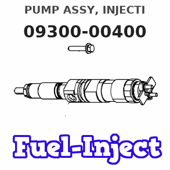
Information pump assy, injecti
Nozzle:
0935002470
Rating:
KIT List:
| Body assy, injecti | 1904400300 |
| Governor assy, mec | 1908900250 |
| Timer assy, automa | 0918030050 |
| Pump assy, fuel fe | 1922900060 |
| Pump assy, fuel fe | 1922900060 |
| Pump assy, fuel fe | 1922900060 |
Components :
| 001. | PUMP ASSY, INJECTI | 09300-00400 |
| 002. | SWITCH KIT, CONTRO | 09009-90241 |
| 003. | BODY ASSY, INJECTI | 09010-03691 |
| 004. | GOVERNOR ASSY, MEC | 09080-07760 |
| 005. | TIMER ASSY, AUTOMA | 09180-01630 |
| 006. | PUMP ASSY, FUEL FE | 09210-00561 |
| 007. | PUMP ASSY, FUEL FE | 09210-01140 |
| 008. | PUMP ASSY, FUEL FE | 09210-01551 |
Scheme ###:
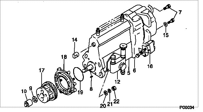
| 000. | [01] | 09300-00400 | PUMP ASSY, INJECTI | ME016082 |
| 005. | [01] | 09010-03691 | BODY ASSY, INJECTI | ME016010 |
| 006. | [01] | 09080-07760 | GOVERNOR ASSY, MEC | ME703262 |
| 007. | [06] | 94904-70620 | BOLT, W/WASHER | ME703359 |
| 008. | [01] | 94913-00190 | KEY, WOODRUFF | ME703361 |
| 009. | [01] | 94901-50500 | WASHER, SPRING | ME008373 |
| 010. | [01] | 09001-20260 | NUT, TIMER ROUND | ME703450 |
| 012. | [01] | 09210-01551 | PUMP ASSY, FUEL FE | ME703037 |
| 012. | [01] | 09210-01140 | PUMP ASSY, FUEL FE | ME016021 |
| 012. | [01] | 09210-00561 | PUMP ASSY, FUEL FE | ME029078 |
| 014. | [01] | 09001-80190 | COVER, CONTROL RAC | ME022416 |
| 015. | [01] | 90200-06511 | WASHER, PLATE | ME703364 |
| 016. | [01] | 09009-90241 | SWITCH KIT, CONTRO | ME016025 |
| 017. | [01] | 09180-01630 | TIMER ASSY, AUTOMA | ME016120 |
| 018. | [01] | 09006-00180 | COVER SUB-ASSY, TI | ME016070 |
| 019. | [01] | 94914-03990 | O-RING | MH035501 |
| 020. | [04] | 94901-15020 | WASHER, STEEL PLAT | MH005068 |
| 021. | [04] | 90258-10001 | WASHER, SPRING | MC327716 |
| 022. | [04] | 91266-10081 | NUT, HEXAGON | MF430122 |
Include in #3:
09300-00400
as PUMP ASSY, INJECTI
Cross reference number
| Part num | Firm num | Firm | Name |
| 09300-00400 | ME016082 | PUMP ASSY, INJECTI | |
| ME016082 | MITSUBISHI | PUMP ASSY, INJECTI |
Information:
Start By:a. remove valve covers1. Turn the flywheel with Tool (C) until there is clearance between the rocker arms and valve bridges. 2. Engage Tool (A) with the rocker arm, and move Tool (A) against the valve spring force until push rod (1) can be removed.3. Remove the other push rod for the same cylinder. Mark each push rod so it can be installed in its original position. 4. Use Tool (B) to remove valve lifter (2).5. Remove the other valve lifter for the same cylinder. Mark each valve lifter so it can be installed in its original position. 6. Remove spring (3) from lifter (2).7. Inspect spring (3). See Guideline For Reusable Parts, SEBF8066. 8. Identify the location of each valve bridge (4), then remove them.Install Push Rods, Valve Lifters & Valve Bridges
1. Put clean engine oil on each bridge dowel and the bore of each bridge. Install bridges (1) in their original position.2. Use the following procedure to adjust the valve bridges.a. Put clean SAE 30 Engine Oil in the lubrication passage of the bridge.b. Press straight down on the top contact surface of the bridge with a force of 4.45 to 44.50 N (1 to 10 lb).c. Turn the adjusting screw clockwise until the oil film in the lubrication passage of the bridge moves inward.d. Turn the adjusting screw an additional 20 to 30 degrees (1/3 to 1/2 of a flat on the hex nut).e. Hold the adjusting screw in position, and tighten the locknut to a torque of 26 to 34 N m (19 to 25 lb ft).f. Do this procedure for both bridges. Put clean engine oil on the top contact surface of both bridges. 3. Install spring (3) on valve lifter (2). 4. Fasten Tool (A) to valve lifter (2).5. Immerse valve lifter (2) in clean engine oil; then install it in its original position.6. Install the other valve lifter for the same cylinder. 7. Engage Tool (B) with the rocker arm, and move Tool (B) against the valve spring force until push rods (4) can be installed in their original position.8. Use Tool (C) to turn the flywheel so the remaining push rods can be installed. Be sure there is clearance at the rocker arms and valve bridges before compressing the valve pump.9. Check the valve clearance settings. The clearance for the intake valves is 0.38 mm (.015 in). The clearance for the exhaust valve is 0.76 mm (.030 in). See the topic "Valve Clearance Setting" in Testing & Adjusting.End By:a. install valve covers
1. Put clean engine oil on each bridge dowel and the bore of each bridge. Install bridges (1) in their original position.2. Use the following procedure to adjust the valve bridges.a. Put clean SAE 30 Engine Oil in the lubrication passage of the bridge.b. Press straight down on the top contact surface of the bridge with a force of 4.45 to 44.50 N (1 to 10 lb).c. Turn the adjusting screw clockwise until the oil film in the lubrication passage of the bridge moves inward.d. Turn the adjusting screw an additional 20 to 30 degrees (1/3 to 1/2 of a flat on the hex nut).e. Hold the adjusting screw in position, and tighten the locknut to a torque of 26 to 34 N m (19 to 25 lb ft).f. Do this procedure for both bridges. Put clean engine oil on the top contact surface of both bridges. 3. Install spring (3) on valve lifter (2). 4. Fasten Tool (A) to valve lifter (2).5. Immerse valve lifter (2) in clean engine oil; then install it in its original position.6. Install the other valve lifter for the same cylinder. 7. Engage Tool (B) with the rocker arm, and move Tool (B) against the valve spring force until push rods (4) can be installed in their original position.8. Use Tool (C) to turn the flywheel so the remaining push rods can be installed. Be sure there is clearance at the rocker arms and valve bridges before compressing the valve pump.9. Check the valve clearance settings. The clearance for the intake valves is 0.38 mm (.015 in). The clearance for the exhaust valve is 0.76 mm (.030 in). See the topic "Valve Clearance Setting" in Testing & Adjusting.End By:a. install valve covers