Information pump assy, injecti
Nozzle:
0935002470
Rating:
KIT List:
| Body assy, injecti | 1904400300 |
| Governor assy, mec | 1908900250 |
| Pump assy, fuel fe | 1922900060 |
| Pump assy, fuel fe | 1922900060 |
| Pump assy, fuel fe | 1922900060 |
Components :
| 001. | PUMP ASSY, INJECTI | 09300-00390 |
| 002. | BODY ASSY, INJECTI | 09010-03691 |
| 003. | GOVERNOR ASSY, MEC | 09080-07762 |
| 004. | TIMER ASSY, AUTOMA | 09180-01131 |
| 005. | PUMP ASSY, FUEL FE | 09210-00561 |
| 006. | PUMP ASSY, FUEL FE | 09210-01140 |
| 007. | PUMP ASSY, FUEL FE | 09210-01551 |
Scheme ###:
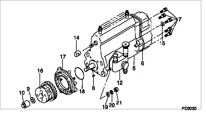
| 000. | [01] | 09300-00390 | PUMP ASSY, INJECTI | ME016081 |
| 005. | [01] | 09010-03691 | BODY ASSY, INJECTI | ME016010 |
| 006. | [01] | 09080-07762 | GOVERNOR ASSY, MEC | ME703262 |
| 007. | [06] | 94904-70620 | BOLT, W/WASHER | ME703359 |
| 008. | [01] | 94913-00190 | KEY, WOODRUFF | ME703361 |
| 009. | [01] | 94901-50500 | WASHER, SPRING | ME008373 |
| 010. | [01] | 09001-20260 | NUT, TIMER ROUND | ME703450 |
| 012. | [01] | 09210-01551 | PUMP ASSY, FUEL FE | ME703037 |
| 012. | [01] | 09210-01140 | PUMP ASSY, FUEL FE | ME016021 |
| 012. | [01] | 09210-00561 | PUMP ASSY, FUEL FE | ME029078 |
| 014. | [01] | 09001-80190 | COVER, CONTROL RAC | ME022416 |
| 015. | [01] | 90200-06511 | WASHER, PLATE | ME703364 |
| 016. | [01] | 09180-01131 | TIMER ASSY, AUTOMA | ME012704 |
| 017. | [01] | 09006-00180 | COVER SUB-ASSY, TI | ME016070 |
| 018. | [01] | 94914-03990 | O-RING | MH035501 |
| 019. | [04] | 94901-15020 | WASHER, STEEL PLAT | MH005068 |
| 020. | [04] | 90258-10001 | WASHER, SPRING | MC327716 |
| 021. | [04] | 91266-10081 | NUT, HEXAGON | MF430122 |
Include in #3:
09300-00390
as PUMP ASSY, INJECTI
Cross reference number
| Part num | Firm num | Firm | Name |
| 09300-00390 | ME016081 | PUMP ASSY, INJECTI | |
| ME016081 | MITSUBISHI | PUMP ASSY, INJECTI |
Information:
1. Remove air compressor outlet hose (1). (Not applicable).2. Remove air compressor air inlet tube (3). (Not applicable).3. Remove air compressor coolant outlet tube (4). (Not applicable)4. Remove turbocharger oil return tube (2). 5. Use Tooling (A) to remove studs (5).6. Turn the flywheel with Tool (B), and remove each bolt (6) as it becomes accessible.7. Turn the flywheel with Tool (B) until the "V" marks on the front timing gears are in alignment.8. Install Tooling (C) through the holes for studs (5) into camshaft rear gear (7).
Tooling (C) must be used to prevent the loss of rear balance weight timing and to keep the camshaft rear gear in place when the camshaft is removed.
9. Tighten Tooling (C) evenly to remove the camshaft rear gear from the camshaft. 10. Remove thrust plate (8).
Be careful not to damage the camshaft bearings. Do not pry the camshaft out of the cylinder block. If resistance to camshaft removal occurs, turn the camshaft so the lobes will align the bearing journals with the camshaft bearing bores.
11. Carefully remove the camshaft and gear (9) from the cylinder block.12. If removal of the camshaft gear is necessary, place the camshaft and gear in a hydraulic press. Place Tool (D) over the camshaft, and press against it to remove the camshaft from the gear.
Be careful not to scratch or mar the finished surfaces of the camshaft.
13. Remove the key from the camshaft.14. If dowel removal is necessary, use Tool (E) to remove the dowel.Install Camshaft
1. Install the key in the camshaft. Be sure the key is seated in the camshaft.2. Install the pin in the rear of the camshaft. Install the pin to a height of 8.51 to 9.01 mm (.335 to .355 in).3. Heat the camshaft drive gear to a maximum temperature of 204° C (400° F), align the groove in the drive gear with the key in the camshaft, and install the camshaft drive gear with the timing marks away from the camshaft.4. Put clean engine oil on the camshaft bearing journals and lobes.5. Carefully install the camshaft into the cylinder block. Do not force the camshaft into position. If resistance to camshaft installation occurs, turn the camshaft so the lobes will align the bearing journals with the camshaft bearing bores. 6. Align the "V" marks on camshaft drive gear (2) and idler gear (3).7. Install thrust plate (1) to hold the camshaft and camshaft drive gear (2) in the cylinder block. 8. Loosen the bolts Tool (B) that hold camshaft rear gear (5) so camshaft rear gear (5) will engage the dowel on the rear of the camshaft.9. After the dowel is engaged, remove Tool (B), and install bolts (4).10. Use Tool (A) to turn the flywheel, and install each of four bolts (4). Tighten bolts (4) to a torque of 23 to 31 N m (17 to 23 lb ft).11. Put 5P-3413 Pipe Sealant with "Teflon" on the threads of studs (6). Use Tooling (C) to install the studs.12. Install