Information pump assy, injecti
Nozzle:
0935001830
Rating:
KIT List:
| Body assy, injecti | 1904400300 |
| Governor assy, mec | 1908900250 |
| Pump assy, fuel fe | 1922900060 |
| Pump assy, fuel fe | 1922900060 |
| Pump assy, fuel fe | 1922900060 |
Components :
| 001. | PUMP ASSY, INJECTI | 09300-00090 |
| 002. | BODY ASSY, INJECTI | 09010-03691 |
| 003. | GOVERNOR ASSY, MEC | 09080-05284 |
| 004. | TIMER ASSY, AUTOMA | 09180-01131 |
| 005. | PUMP ASSY, FUEL FE | 09210-00561 |
| 006. | PUMP ASSY, FUEL FE | 09210-01140 |
| 007. | PUMP ASSY, FUEL FE | 09210-01551 |
Scheme ###:
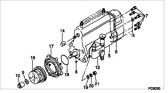
| 000. | [01] | 09300-00091 | PUMP ASSY, INJECTI | ME016006 |
| 005. | [01] | 09010-03691 | BODY ASSY, INJECTI | ME016010 |
| 006. | [01] | 09080-05284 | GOVERNOR ASSY, MEC | ME016018 |
| 007. | [06] | 94904-70620 | BOLT, W/WASHER | ME703359 |
| 008. | [01] | 94913-00190 | KEY, WOODRUFF | ME703361 |
| 009. | [01] | 94901-50500 | WASHER, SPRING | ME008373 |
| 010. | [01] | 09001-20260 | NUT, TIMER ROUND | ME703450 |
| 012. | [01] | 09210-01551 | PUMP ASSY, FUEL FE | ME703037 |
| 012. | [01] | 09210-01140 | PUMP ASSY, FUEL FE | ME016021 |
| 012. | [01] | 09210-00561 | PUMP ASSY, FUEL FE | ME029078 |
| 014. | [01] | 09001-80190 | COVER, CONTROL RAC | ME022416 |
| 015. | [01] | 90200-06511 | WASHER, PLATE | ME703364 |
| 016. | [01] | 09180-01131 | TIMER ASSY, AUTOMA | ME012704 |
| 017. | [01] | 09006-00130 | COVER SUB-ASSY, TI | ME016038 |
| 018. | [01] | 94914-03990 | O-RING | MH035501 |
| 019. | [04] | 94901-15020 | WASHER, STEEL PLAT | MH005068 |
| 020. | [04] | 90258-10001 | WASHER, SPRING | MC327716 |
| 021. | [04] | 91266-10081 | NUT, HEXAGON | MF430122 |
Cross reference number
| Part num | Firm num | Firm | Name |
| 09300-00090 | PUMP ASSY, INJECTI | ||
| ME016006 | MITSUBISHI | PUMP ASSY, INJECTI |
Information:
Typical Example1. Disconnect wire (1) from Jake Brake. Remove three bolts (2) and remove the Jake Brake.
Typical Example2. Remove Jake Brake exhaust bridge assemblies (3). The following steps are for the installation of the Jake Brake.3. Install Jake Brake exhaust bridge assemblies (3) in the same orientation as illustrated.4. Position Jake Brake assembly and install bolts (2). Connect wire (1).End By:a. install valve cover assemblies as they are illustrated.Disassemble & Assemble Jake Brake
Remove the control valve and slave piston carefully. Control valves are under load from the control valve springs. The slave piston is retained by springs that are under heavy compression. Remove with care to avoid injury.
Start By:a. remove Jake Brake 1. Apply finger pressure to the control valve cover (2). Rotate retaining ring (1) to the slot in the housing. Remove the retaining ring. Release finger pressure slowly. Remove insert (3), spring (4), spring (5), collar (6) and control valve (7).2. Remove solenoid valve (8). Remove three O-ring seals (9) from housing.3. Remove locknut (11). Back out adjusting screw (10) until slave piston is fully retracted.4. Clamp and depress retainer (18) until retainer is 1 mm (.030 in) below the retaining ring groove. Remove retaining ring (19). Back out clamp until springs are loose. Remove clamp. Remove retainer (18), spring (17), spring (16) and slave piston (15).5. Remove anti-rotation pin (13) and washer (12). Remove master piston assembly (14).The following steps are for the assembly of the Jake Brake.6. Inspect master piston assembly (14) for damage. The piston surface must be free of score or wear marks. The piston must move freely in the housing bore. Inspect the spring to insure it is not broken.7. Compress the return spring in the master piston assembly with a pick or probe. While compressed, insert a small pin into the access hole and remove pick or probe. Insert the master piston assembly. Install anti-rotation pin (13) and washer (12) into the housing and remove small pin. The return spring will then be retained by the anti-rotation pin.8. Install slave piston (15), spring (16), spring (17), and retainer (18). Clamp and compress the slave piston retainer until retainer is about 1 mm (.030 in) below the retaining ring groove. Install retaining ring (19). Release clamp.9. Screw adjusting screw (12) in until touching slave piston assembly. Install locknut (11).10. Check the O-ring seals for the solenoid valve for wear or damage. Replace as required. Install three O-ring seals (9) on the solenoid valve. Install solenoid valve (8). Tighten the solenoid to a torque of 7 N m (60 lb in). Be sure O-ring seals are seated properly. Be careful not to twist or unseat O-ring seals while installing.11. Install control valve (7). Install collar (6) with longer sleeve area up. Install spring (4), spring (5), retainer (3) and control valve cover (2). Depress control valve cover with finger. Install retaining ring (1). Rotate retaining ring so the retaining ring ears are located away from the slot in the housing. Release finger