Information coupling assy
Rating:
Scheme ###:
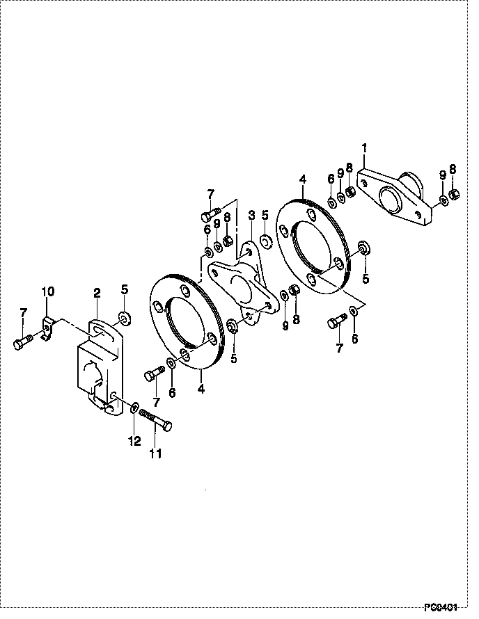
| 000. | [01] | 09250-00260 | COUPLING ASSY | |
| 001. | [01] | 09255-10240 | BLOCK, COUPLING | 09255-10240 |
| 002. | [01] | 09241-50311 | FLANGE, COUPLING | 09241-50310 |
| 003. | [01] | 09243-70040 | COUPLING, CROSS | |
| 004. | [08] | 09243-90050 | PLATE, COUPLING | 09243-90050 |
| 005. | [08] | 09246-10021 | BUSHING, COUPLING | 09246-10020 |
| 006. | [08] | 09246-20010 | PLATE, COUPLING PL | 09246-20010 |
| 007. | [08] | 94904-00591 | BOLT, HEXAGON | 94904-00591 |
| 008. | [08] | 90196-08651 | NUT, HEXAGON | |
| 009. | [08] | 90258-08001 | WASHER, SPRING | 90258-08001 |
| 010. | [02] | 09241-70010 | WASHER, COUPLING S | 09241-70010 |
| 011. | [01] | 94904-04600 | BOLT, HEXAGON | 94904-04600 |
| 012. | [01] | 90258-10001 | WASHER, SPRING | 90258-10001 |
Include in #3:
09250-00260
as COUPLING ASSY
Cross reference number
| Part num | Firm num | Firm | Name |
| 09250-00260 | COUPLING ASSY |
Information:
3. With dial indicator set at "0" (zero) at location (A), turn the crankshaft and read the indicator at locations (B), (C) and (D).4. The difference between lower and higher measurements taken at all four points must not be more than 0.20 mm (.008 in.)Bore Runout
Write the dial indicator measurements with their positive (+) and negative (-) notation (signs). This notation is necessary when the calculations are made in the chart correctly. 1. Fasten a dial indicator to the crankshaft flange so the 7H1940 Universal Attachment of the indicator is in contact with the inner flywheel housing bore at location (C). Adjust the dial indicator to "0" (zero). Push the crankshaft up against the top crankshaft bearing. Write the measurement for bearing clearance on line 1 in column (C) of the chart.2. Divide the measurement from Step 1 by 2. Write this number on line in columns (B) and (D). 3. Turn the crankshaft to put the dial indicator at (A). Adjust the dial indicator to "0" (zero).4. Turn the crankshaft counterclockwise to put the dial indicator at (B). Write the measurement in the chart.5. Turn the crankshaft counterclockwise to put the dial indicator at (C). Write the measurement in the chart.6. Turn the crankshaft counterclockwise to put the dial indicator at (D). Write the measurement in the chart.7. Add lines I and II by columns. 8. Subtract the smaller number from the larger number in line II in columns (B) and (D). The result is the horizontal "eccentricity" (out of round). Line III, column (C) is the vertical eccentricity. 9. On the graph for total eccentricity, find the point of intersection of the lines for vertical eccentricity and horizontal eccentricity.10. If the point of intersection is in the range marked "Acceptable" the bore is in alignment. If the point of intersection is in the range marked "Not Acceptable", the flywheel housing must be changed.
Write the dial indicator measurements with their positive (+) and negative (-) notation (signs). This notation is necessary when the calculations are made in the chart correctly. 1. Fasten a dial indicator to the crankshaft flange so the 7H1940 Universal Attachment of the indicator is in contact with the inner flywheel housing bore at location (C). Adjust the dial indicator to "0" (zero). Push the crankshaft up against the top crankshaft bearing. Write the measurement for bearing clearance on line 1 in column (C) of the chart.2. Divide the measurement from Step 1 by 2. Write this number on line in columns (B) and (D). 3. Turn the crankshaft to put the dial indicator at (A). Adjust the dial indicator to "0" (zero).4. Turn the crankshaft counterclockwise to put the dial indicator at (B). Write the measurement in the chart.5. Turn the crankshaft counterclockwise to put the dial indicator at (C). Write the measurement in the chart.6. Turn the crankshaft counterclockwise to put the dial indicator at (D). Write the measurement in the chart.7. Add lines I and II by columns. 8. Subtract the smaller number from the larger number in line II in columns (B) and (D). The result is the horizontal "eccentricity" (out of round). Line III, column (C) is the vertical eccentricity. 9. On the graph for total eccentricity, find the point of intersection of the lines for vertical eccentricity and horizontal eccentricity.10. If the point of intersection is in the range marked "Acceptable" the bore is in alignment. If the point of intersection is in the range marked "Not Acceptable", the flywheel housing must be changed.