Information pump assy, fuel fe
Rating:
KIT List:
| Pump assy, fuel fe | 1922900070 |
| Pump assy, fuel fe | 1922900070 |
| Pump assy, fuel fe | 1922900070 |
Scheme ###:
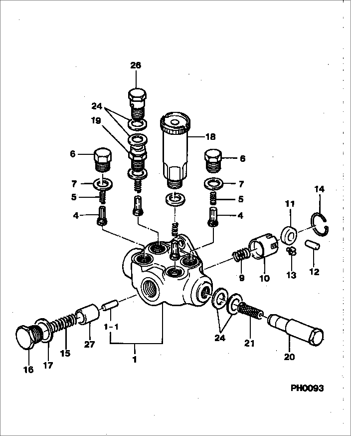
| 000. | [01] | 09210-02510 | PUMP ASSY, FUEL FE | |
| 001. | [01] | 09212-00500 | HOUSING SUB-ASSY, | 22564-1180A |
| 001-001. | [01] | 09216-80160 | ROD, FEED PUMP PUS | 22565-1220A |
| 004. | [04] | 09212-10011 | VALVE, FEED PUMP C | 22563-1041A |
| 005. | [04] | 09212-40010 | SPRING, FEED PUMP | 22562-1020A |
| 006. | [02] | 09212-60010 | PLUG, FEED PUMP CH | 22845-1350A |
| 007. | [04] | 09212-50010 | GASKET, CHECK VALV | 22847-1680A |
| 009. | [01] | 09217-30010 | SPRING, FEED PUMP | 22567-1040A |
| 010. | [01] | 09217-40041 | TAPPET, FEED PUMP | 22568-1151A |
| 011. | [01] | 09217-60021 | ROLLER, FEED PUMP | 22569-1070A |
| 012. | [01] | 09217-80030 | PIN, FEED PUMP TAP | 22571-1060A |
| 013. | [02] | 09217-90081 | BLOCK, FEED PUMP T | 22572-1120A |
| 014. | [01] | 94907-20940 | RING, SNAP | 22887-1160A |
| 015. | [01] | 09218-20130 | SPRING, FEED PUMP | 22567-1190A |
| 016. | [01] | 09218-40021 | PLUG, FEED PUMP PI | 22845-1360A |
| 017. | [01] | 94901-81240 | WASHER, COPPER PLA | 22847-1690A |
| 018. | [01] | 09213-00220 | PUMP SUB-ASSY, PRI | 22509-1160A |
| 018. | [01] | 09213-00360 | PUMP SUB-ASSY, PRI | |
| 019. | [01] | 09212-70040 | SUPPORT, VALVE | 22841-1970A |
| 020. | [01] | 09222-30070 | SCREW, FUEL PIPE H | 22835-1370A |
| 021. | [01] | 09222-00040 | FILTER, FEED PUMP | 22574-1040A |
| 024. | [04] | 94901-02490 | WASHER | 22877-1100A |
| 026. | [01] | 94918-00310 | SCREW, HOLLOW | 22835-1310A |
| 027. | [01] | 09217-10011 | PISTON, FEED PUMP | 22566-1200A |
Include in #3:
Cross reference number
| Part num | Firm num | Firm | Name |
| 09210-02510 | PUMP ASSY, FUEL FE |
Information:
The following installation procedures are to be used in conjunction with the Special Instruction, SEHS9329, "Installation of Automatic Ether Injection System". This instruction outlines the extra steps needed to install components of the MPPS system along with routing and clipping of harnesses.
Before starting the installation procedure, make certain that the machine disconnect switch is in the OFF position.Do not perform any procedure, outlined in this publication, or order any parts until you read and understand the information contained within.Reference: Service Manual, SENR4705-02 and Special Instruction, SEHS9329.Retrofit In Conjunction With AEIS Retrofit
Necessary Parts
The following parts list shows some part numbers in the deleted column. This means that these parts are called out on the AEIS retrofit instructions but should not be ordered, since they are replaced by different parts for MPPS. Installation of 3E3778 Ether Control Group
The 3E3778 Control Group is substituted for the 9X5303 Control Group called out in the Automatic Ether Injection System Special Instruction, SEHS9329. Follow the same installation procedure used for the 9X5303 Control Group.Substitute a 3E3779 Film for the 9X4542 Film. If an MPPS identification film is needed for a language other than English, refer to the following chart for the part number of the film for a specific language. Installation of 3E3530 Electronic Control Group [(PWM) Oil Pressure Sensor]
1. Remove the 6T7663 Oil Pressure Switch and adapter from the turbo oil adapter on the right rear of the engine (switch on bottom port with 405-GY attached to it). 2. Install a 3E5276 Adapter (1) in the port using a 3J7354 Seal and a 6V4589 O-ring Seal.3. Install 3E3530 Electronic Control Group (2) [PWM Oil Pressure Sensor] onto 3E5276 Adapter.4. Place a 6V1874 Grommet over the tubular portion of the 3E3530 Electronic Control Group (2). 5. Using a 5P7468 Clip (3) and 5P7469 Clip (4), install the 3E3530 Electronic Control Group (2) to the flywheel housing with a 4L9337 Bolt (5) and 5P1075 Washer (6).6. Install a 9X3495 Clip Assembly (7) to the flywheel housing as shown using an available bolt.Installation of Wiring Harnesses
Installation of 8X9862 Ether (Rear Cab) Wiring Harness
The 8X5003 Harness Assembly, called out in the AEIS Special Instruction, SEHS9329, is replaced by a different cab harness which has additional connections for the oil pressure sensor and EMS oil pressure switch input.Follow the installation procedure outlined in the AEIS Special Instruction for the 8X5003 Harness Assembly. In addition, the following steps need to be performed.1. Cut the 6A3359 Wire to approximately 3 dm (11.82 in). Strip one end and attach a 7N7779 Socket.Insert the socket into location #1 of the 7N9738 Housing.Insert 9G3695 Plug into location #2 of the 7N9738 Housing. 2. Locate wire 405-GY on the main cab harness near the connector exiting the cab wall on the right hand side, as shown by arrow.Cut this wire close to the connector. Splice it and the wire just assembled using an 8S4626 Splice. Be sure to splice to the portion of the wire that goes into the cab harness.3. Connect the 7N9738