Information pump assy, fuel fe
Rating:
KIT List:
| Pump assy, fuel fe | 1922900060 |
| Pump assy, fuel fe | 1922900060 |
| Pump assy, fuel fe | 1922900060 |
Scheme ###:
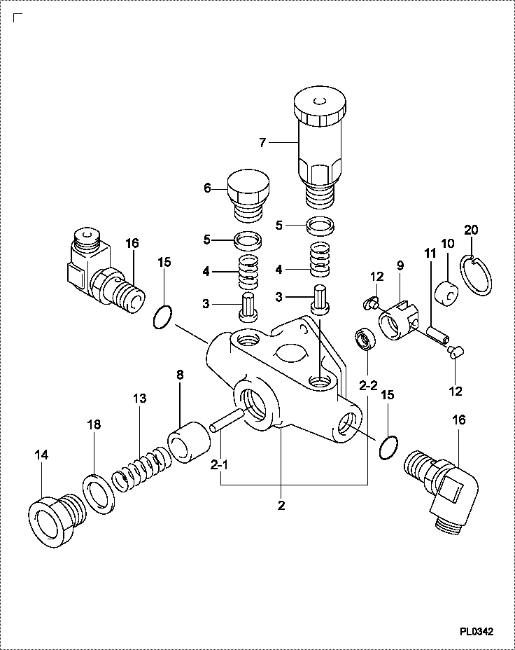
| 000. | [01] | 09210-02400 | PUMP ASSY, FUEL FE | |
| 002. | [01] | 09212-00540 | HOUSING SUB-ASSY, | |
| 002-001. | [01] | 09216-80150 | ROD, FEED PUMP PUS | |
| 002-002. | [01] | 94915-02700 | SEAL, OIL | |
| 003. | [02] | 09212-10011 | VALVE, FEED PUMP C | |
| 004. | [02] | 09212-40010 | SPRING, FEED PUMP | |
| 005. | [02] | 09212-50010 | GASKET, CHECK VALV | |
| 006. | [01] | 09212-60010 | PLUG, FEED PUMP CH | |
| 007. | [01] | 09213-00260 | PUMP SUB-ASSY, PRI | |
| 008. | [01] | 09217-10011 | PISTON, FEED PUMP | |
| 009. | [01] | 09217-40050 | TAPPET, FEED PUMP | |
| 010. | [01] | 09217-60010 | ROLLER, FEED PUMP | |
| 011. | [01] | 09217-80040 | PIN, FEED PUMP TAP | |
| 012. | [02] | 09217-90070 | BLOCK, FEED PUMP T | |
| 013. | [01] | 09218-20100 | SPRING, FEED PUMP | |
| 014. | [01] | 09218-40021 | PLUG, FEED PUMP PI | |
| 015. | [02] | 09013-90030 | O-RING | |
| 016. | [02] | 09007-30060 | NIPPLE, ELBOW | |
| 018. | [01] | 94901-81240 | WASHER, COPPER PLA | |
| 020. | [01] | 94907-20940 | RING, SNAP |
Include in #3:
Cross reference number
| Part num | Firm num | Firm | Name |
| 09210-02400 | PUMP ASSY, FUEL FE |
Information:
NEXG4519 Contents
1. NEXG4519 Service Program Module. 2. Operating Manual SEHS9203. NEEG2458 Case Lid Label (Not shown). NEEG2457 DDT Back Label (Not shown). NEEG2456 Pocket Card (Not shown). The NEEG forms may not be included in automatic updates of NEXG4519.Glossary
CDegree CentigradeCALCalibrationCSPCustomer Specified ParameterCYLCylinderDDTDigital Diagnostic ToolDIAGDiagnosticENGEngineEPROMErasable Programmable Read Only MemoryEUIElectronic Unit InjectorFDegree FahrenheitFRCFuel Ratio ControlFREQFrequencyFUNCFunctionHPHorsepowerHzCycles Per SecondIDIdentificationkPaKilopascalkWKilowattLBPoundsfootLCDLiquid Crystal DisplayLOLowLOGLoggedMAXMaximumMINMinimumModModuleNmNewton-meterPOSPositionPRPressurePSIPounds Per Square InchPWPulse WidthPWMPulse Width ModulatedRAM Random Access MemoryROMRead Only MemoryRPMRevolutions Per MinuteSPMService Program ModuleTATTLETattletaleTELTop Engine RPM LimitTEMPTemperature%PercentFeatures
Diagnostic Fault Codes
The DDT will display active diagnostic fault codes, active diagnostic logged fault codes, and inactive diagnostic logged faults codes.The display of diagnostic logged fault codes will also include the number of occurrences, the first occurrence, and the last occurrence of the specific diagnostic fault.Engine Status
The DDT will display:* Coolant Temperature* Engine RPM* Engine Timing* Fuel Positions* Throttle Position* Engine PressuresCustomer Specified Parameters (CSP)
The DDT will display and modify:* Engine Rating* Low Idle Engine RPM* Top Engine Limit* Vehicle IDEngine Rating
The DDT will display the available rating descriptions for rated power, rated torque, maximum top engine RPM, and minimum top engine RPM.Sensor Calibration
The DDT will calibrate the boost sensor.External Sensors
The DDT will display the duty cycle and frequency of a modulated signal present at the PWM Sensor Port.Cylinder Status
The DDT will display and modify the status of cylinders #1 through #6 as (POWERED or CUTOUT).System Security
The DDT will display and change customer passwords which protect all Customer Specified Parameters, specified diagnostic logged faults, and customer passwords themselves.Also the DDT will display the tattletales for Customer Specified Parameters, customer passwords, or a total tattletale for the whole system providing an accounting method for changes made to Customer Specified Parameters and customer passwords.Scrolling Access
The DDT will go to the next mode when the SELECT MODE key is pressed and will go to the next function when the SELECT FUNC key is pressed.Direct Access
The DDT will go to the mode or function whose number is present in the MODE/FUNC window when the ENTER key is pressed.DDT Description
1 -LCD Screen: Displays engine status information, CSP information, CSP modifications, and instructions. The MODE/FUNC window is in the upper right or the lower right portion of the LCD followed by a The Input Cursor will be shown on the LCD when information can be entered onto the LCD from the keypad.If the Input Cursor is not displayed, then no information can be entered into the LCD from the keypad.2 -CONTROL Port: The CONTROL port communicates with the Electronic Control Module (ECM) through the 8T5275 Cable Assembly.3 -PWM SENSOR Port: The PWM SENSOR port measures duty cycle and frequency of a modulated signal using the 8T5277 Cable (probe).4 -CLEAR Key: Pressing the CLEAR key will:* Clear a Fault Display* Clear a Warning Display* Clear data entered while entering data to change a Customer Specified Parameter* Place 01 in the MODE/FUNC window.5 -SELECT MODE Key: Pressing the SELECT MODE key will scroll to the next available Mode.6 -SELECT FUNC Key: Pressing the SELECT FUNC key will scroll to the next available