Information pump assy, fuel fe
PUMP ASSY, FUEL FE
DA
- CURRENT PARTS:092100-3170
Rating:
KIT List:
| Pump assy, fuel fe | 1922900060 |
| Pump assy, fuel fe | 1922900060 |
| Pump assy, fuel fe | 1922900060 |
| Pump assy, fuel fe | 1922900060 |
| Pump assy, fuel fe | 1922900060 |
| Pump assy, fuel fe | 1922900060 |
| Pump assy, fuel fe | 1922900060 |
| Pump assy, fuel fe | 1922900060 |
Scheme ###:
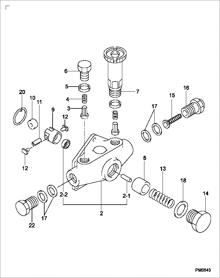
| 000. | [01] | 09210-02080 | PUMP ASSY, FUEL FE | 22570-1410 |
| 002. | [01] | 09212-00370 | HOUSING SUB-ASSY, | 22580-1210A |
| 002-001. | [01] | 09216-80150 | ROD, FEED PUMP PUS | 22565-1250A |
| 003. | [02] | 09212-10011 | VALVE, FEED PUMP C | 22563-1041A |
| 004. | [02] | 09212-40010 | SPRING, FEED PUMP | 22562-1020A |
| 005. | [02] | 09212-50010 | GASKET, CHECK VALV | 22847-1680A |
| 006. | [01] | 09212-60010 | PLUG, FEED PUMP CH | 22845-1350A |
| 007. | [01] | 09213-00220 | PUMP SUB-ASSY, PRI | 22509-1160A |
| 008. | [01] | 09217-10011 | PISTON, FEED PUMP | 22566-1200A |
| 009. | [01] | 09217-40050 | TAPPET, FEED PUMP | 22568-1170A |
| 010. | [01] | 09217-60010 | ROLLER, FEED PUMP | 22569-1110A |
| 011. | [01] | 09217-80040 | PIN, FEED PUMP TAP | 22571-1090A |
| 012. | [02] | 09217-90070 | BLOCK, FEED PUMP T | 22572-1070A |
| 013. | [01] | 09218-20100 | SPRING, FEED PUMP | 22567-1170A |
| 014. | [01] | 09218-40021 | PLUG, FEED PUMP PI | 22845-1360A |
| 015. | [01] | 09222-00040 | FILTER, FEED PUMP | 22574-1040A |
| 016. | [01] | 09222-30070 | SCREW, FUEL PIPE H | 22835-1370A |
| 017. | [04] | 94901-02490 | WASHER | 22877-1100A |
| 018. | [01] | 94901-81240 | WASHER, COPPER PLA | 22847-1690A |
| 020. | [01] | 94907-20940 | RING, SNAP | 22887-1160A |
| 022. | [01] | 94918-00310 | SCREW, HOLLOW | 22835-1310A |
Include in #3:
09210-02080
as PUMP ASSY, FUEL FE
Cross reference number
| Part num | Firm num | Firm | Name |
| 09210-02080 | 22570-1410 | PUMP ASSY, FUEL FE | |
| 22570-1410A | HINO | PUMP ASSY, FUEL FE | |
| 22570-1410 | HINO | PUMP ASSY, FUEL FE |
Information:
When a remanufactured engine is to be installed as part of the EUI Conversion or the heat shields are to be removed, SEHS9256-01 Thermal Heat Shield Removal and the recommended parts must also be ordered.
On Page 12 and 13 of SEHS9256-01 complete Steps 9 and 11 before installing the engine in the truck. This allows you to drill the plate without removing it from the truck chassis.Parts Needed
Cab Components
Remove the back cab cover and upper air tank to allow easier access to many of the items. This tank will be replaced upon completion of this instruction. One of the existing hose from the governor tank will be install in an extra outlet of the large tank when it is installed back into the cab.Removals
The following items may be removed before any installation is started or when you start working in a particular area.
Brake Control Group (Reference Only)Remove items 19 and 29 from the brake control group. Retain all hardware for later installation.
Governor Control Group (Without Elevated Low Idle) 4YC1-1508, 6JC1-83
Part 1 of 2, Governor Control Group (With Elevated Low Idle) 4YC1509-Up, 6JC84-Up
Part 2 of 2, Governor Control Group (With Elevated Low Idle) 4YC1509-Up, 6JC84-UpAdd 2D3406 Plug in the hole where the elevated low idle switch was located.Add 5H4778 Elbow into the tee where 3S6115 Tee (item 44) was removed. Do not remove 8X7013 Retainer (Item 30). Remove 9G9287 Engine Shutdown Control, plug the harness breakout with 9G3670 Housing and seven 9G3695 Plugs. Insert the connector back in the clip.Chassis Components
Governor Control Group (Chassis) Remove Many of these items may have been removed with the engine EUI retrofit.Cab Junction Panel (Outside)
1. Disconnect the batteries. 2. Disconnect the VE connectors from the panel. 3. Remove the battery disconnect cables. 4. Cut an opening for the EUI 40 pin engine harness connector and an opening for the disconnect cables as shown in the illustration above. 5. Install the disconnect cables.Junction Panel (Inside Cab)
Existing Cab Harness
Refer to SEHS8038 Use Of 6V4810 VE Connector Tool Group or SEHS9065 Use of CE Connector Tools for removal and installation of wires.
Always use the correct tool when removing or installing sockets in a connector. If the proper tool is not used the connector will be damaged. 1. Install the EUI harness connector with four 8T9405 Bolts, 8C9660 Washers and 5C8312 Nuts. The connector goes in the cutout from the INSIDE of the cab. The bolts are installed from outside of the cab. 2. Remove the following wires from the large VE connector which is part of the existing main cab harness:* Wire 407-PK Loc. 2* Wire 418-WH Loc. 4* Wire 310-PU Loc. 5. Wire may not be present on some trucks.* Wire 327-PK Loc. 7, Cut