Information pump assy, fuel fe
Rating:
KIT List:
| Pump assy, fuel fe | 1922900060 |
| Pump assy, fuel fe | 1922900060 |
| Pump assy, fuel fe | 1922900060 |
| Pump assy, fuel fe | 1922900060 |
| Pump assy, fuel fe | 1922900060 |
Scheme ###:
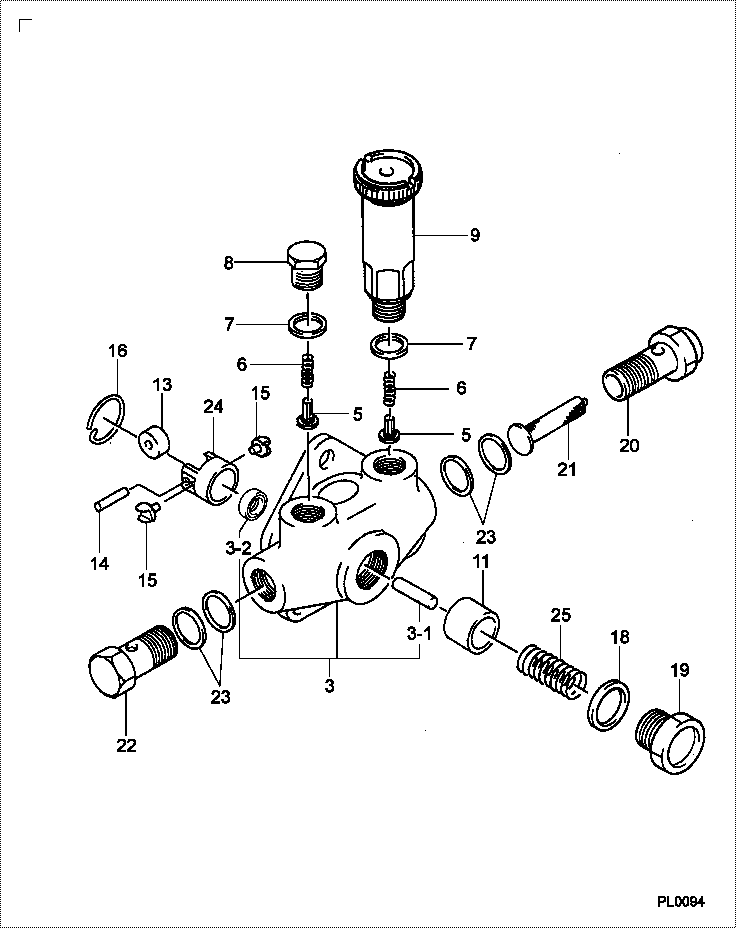
| 000. | [01] | 09210-02020 | PUMP ASSY, FUEL FE | ME703799 |
| 003. | [01] | 09212-00171 | HOUSING SUB-ASSY, | ME702218 |
| 003-001. | [01] | 09216-80150 | ROD, FEED PUMP PUS | ME702219 |
| 003-001. | [1C] | 09216-80070 | ROD, FEED PUMP PUS | ME022296 |
| 003-001. | [1C] | 09216-80060 | ROD, FEED PUMP PUS | ME022295 |
| 003-001. | [1C] | 09216-80050 | ROD, FEED PUMP PUS | ME022294 |
| 003-001. | [1C] | 09216-80040 | ROD, FEED PUMP PUS | ME022293 |
| 003-001. | [1C] | 09216-80030 | ROD, FEED PUMP PUS | ME022292 |
| 003-001. | [1C] | 09216-80010 | ROD, FEED PUMP PUS | ME022291 |
| 003-002. | [01] | 94915-00970 | SEAL, OIL | ME743802 |
| 003-002. | [01] | 94915-02700 | SEAL, OIL | ME736497 |
| 005. | [02] | 09212-10011 | VALVE, FEED PUMP C | ME702220 |
| 006. | [02] | 09212-40010 | SPRING, FEED PUMP | ME702221 |
| 007. | [02] | 09212-50010 | GASKET, CHECK VALV | ME702222 |
| 008. | [01] | 09212-60010 | PLUG, FEED PUMP CH | ME702223 |
| 009. | [01] | 09213-00220 | PUMP SUB-ASSY, PRI | ME702224 |
| 011. | [01] | 09217-10011 | PISTON, FEED PUMP | ME702225 |
| 013. | [01] | 09217-60010 | ROLLER, FEED PUMP | ME702227 |
| 014. | [01] | 09217-80010 | PIN, FEED PUMP TAP | ME702228 |
| 015. | [02] | 09217-90050 | BLOCK, FEED PUMP T | ME702229 |
| 016. | [01] | 94907-20940 | RING, SNAP | ME702234 |
| 018. | [01] | 94901-81240 | WASHER, COPPER PLA | ME702233 |
| 019. | [01] | 09218-40021 | PLUG, FEED PUMP PI | ME702230 |
| 020. | [01] | 09222-30070 | SCREW, FUEL PIPE H | ME702232 |
| 021. | [01] | 09222-00040 | FILTER, FEED PUMP | ME702231 |
| 022. | [01] | 94918-00310 | SCREW, HOLLOW | ME702236 |
| 023. | [04] | 09022-20050 | WASHER, FUEL PIPE | ME703277 |
| 024. | [01] | 09217-40030 | TAPPET, FEED PUMP | ME702226 |
| 025. | [01] | 09218-20020 | SPRING, FEED PUMP | ME702024 |
Include in #3:
Cross reference number
| Part num | Firm num | Firm | Name |
| 09210-02020 | ME703799 | PUMP ASSY, FUEL FE | |
| ME703799 | MITSUBISHI | PUMP ASSY, FUEL FE |
Information:
Do not perform any procedure outlined in this publication or order any parts until you read and understand this information.
Reference: Service Manual.Tool Group Components
The illustration that follows provides a view of the specific tools to aid in tool identification. Individual tool part numbers are given in the charts of the tool group parts.9U-6860 Tool Group For Sleeve Replacement
The following are additional tools and supplies that allow easier completion of the procedures. 4C-6730 Roller Expander Components
Illustration 1: Components of 4C-6730 Roller Expander. Injector Sleeve Removal With Cylinder Head Off The Engine
The following instructions are written with the understanding that the unit injectors have already been removed from the cylinder head.1. Valves, valve springs, and bridge guides may be removed from the specific cylinder(s); however, it is not necessary.2. Remove any loose material or deposits from inside the injector sleeve.
Illustration 2: (1) Nut. (2) Hard washer. (3) Lower pilot. (5) Tap. (15) Guide bushing. (21) Socket. (A) Injector sleeve.3. Insert lower pilot (3) into sleeve (A). Then loosely install hard washer (2) and nut (1) at the bottom side of the cylinder head.4. Select a guide bushing (15) that best fits into the cylinder head injector bore; above the sleeve that is to be removed. The two 4C-8720 and 4C-8721 Guide Bushings supplied with the group are similar in appearance. However, they have slightly different outside diameters. Both should fit into the injector bore in the cylinder head due to tolerance variations in the bore. Use the guide bushing that fits the tightest (with hand force) into the injector bore of a given cylinder. This guide bushing should then be the only one used on this cylinder for further operations that require a guide bushing.Remove the guide bushing from the cylinder head.5. Install tap (5) in injector sleeve (A). Place the pilot bore end of the tap over the pilot of lower pilot (3). Use clean engine oil, or cutting oil, to lubricate the injector sleeve and the cutting threads of tap (5).6. Install previously selected guide bushing (15) over the shank of tap (5) and into the cylinder head injector bore.7. Tighten nut (1) on lower pilot (3). This will prevent the injector sleeve from turning during the thread cutting procedure.8. Place socket (21) on tap (5). Use a 1/2 in drive ratchet wrench to drive tap (5).9. Cut threads in the injector sleeve by turning the tap in a clockwise (CW) direction, until the tap contacts the top surface of lower pilot (3).If the sleeve turns, use the roller expander to tighten the sleeve into the head.10. Remove tap (5) and guide bushing (15). Thoroughly clean any debris from the newly cut threads.11. Remove nut (1) and hard washer (2).
Illustration 3: (3) Lower pilot. (6) Puller screw. (16) Socket. (17) Bridge plate. (18) Bolt. (20) Hard washer. (22) Thrust bearing. (23) Full nut. (25) Puller stud.12. Install puller assembly (6 and 25) into the injector sleeve until the puller stud contacts lower pilot (3). Then retract the puller