Information pump assy, fuel fe
Rating:
Scheme ###:
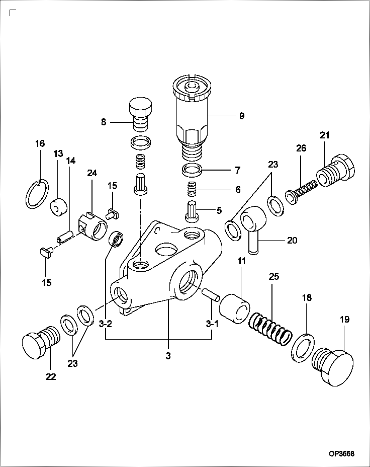
| 000. | [01] | 09210-01391 | PUMP ASSY, FUEL FE | ME039653 |
| 003. | [01] | 09212-00171 | HOUSING SUB-ASSY, | ME702218 |
| 003-001. | [01] | 09216-80150 | ROD, FEED PUMP PUS | ME702219 |
| 003-001. | [1C] | 09216-80070 | ROD, FEED PUMP PUS | ME022296 |
| 003-001. | [1C] | 09216-80060 | ROD, FEED PUMP PUS | ME022295 |
| 003-001. | [1C] | 09216-80050 | ROD, FEED PUMP PUS | ME022294 |
| 003-001. | [1C] | 09216-80040 | ROD, FEED PUMP PUS | ME022293 |
| 003-001. | [1C] | 09216-80030 | ROD, FEED PUMP PUS | ME022292 |
| 003-001. | [1C] | 09216-80010 | ROD, FEED PUMP PUS | ME022291 |
| 003-002. | [01] | 94915-00970 | SEAL, OIL | |
| 003-002. | [01] | 94915-02700 | SEAL, OIL | ME736497 |
| 005. | [02] | 09212-10011 | VALVE, FEED PUMP C | ME702220 |
| 006. | [02] | 09212-40010 | SPRING, FEED PUMP | ME702221 |
| 007. | [02] | 09212-50010 | GASKET, CHECK VALV | ME702222 |
| 008. | [01] | 09212-60010 | PLUG, FEED PUMP CH | ME702223 |
| 009. | [01] | 09213-00220 | PUMP SUB-ASSY, PRI | ME702224 |
| 009. | [01] | 09213-00190 | PUMP SUB-ASSY, PRI | |
| 009. | [01] | 09213-00170 | PUMP SUB-ASSY, PRI | |
| 009. | [01] | 09213-00130 | PUMP SUB-ASSY, PRI | MM501196 |
| 011. | [01] | 09217-10011 | PISTON, FEED PUMP | ME702225 |
| 013. | [01] | 09217-60010 | ROLLER, FEED PUMP | ME702227 |
| 014. | [01] | 09217-80010 | PIN, FEED PUMP TAP | ME702228 |
| 015. | [02] | 09217-90050 | BLOCK, FEED PUMP T | ME702229 |
| 016. | [01] | 94907-20940 | RING, SNAP | ME702234 |
| 018. | [01] | 94901-81240 | WASHER, COPPER PLA | ME702233 |
| 019. | [01] | 09218-40021 | PLUG, FEED PUMP PI | ME702230 |
| 020. | [01] | 94918-10160 | NIPPLE, SWIVELING | ME728845 |
| 021. | [01] | 09222-30070 | SCREW, FUEL PIPE H | ME702232 |
| 022. | [01] | 94918-00310 | SCREW, HOLLOW | ME702236 |
| 023. | [04] | 09022-20070 | WASHER, FUEL PIPE | ME702217 |
| 024. | [01] | 09217-40030 | TAPPET, FEED PUMP | ME702226 |
| 025. | [01] | 09218-20040 | SPRING, FEED PUMP | |
| 026. | [01] | 09222-00040 | FILTER, FEED PUMP | ME702231 |
Include in #3:
09210-01391
as PUMP ASSY, FUEL FE
Cross reference number
| Part num | Firm num | Firm | Name |
| 09210-01391 | ME039653 | PUMP ASSY, FUEL FE |
Information:
The clutch is a dry single disc type which connects and disconnects engine power through the clutch shift shaft.When the operation for clutch disengagement is done, the clutch release lever is pushed. Since the clutch release lever pivots about the release lever pin in the release lever support provided in the clutch cover, the pressure spring is compressed, causing the clutch disc clamped between the engine flywheel and pressure plate to become free and cut power transmission. When the operation for clutch engagement is done, the pressure spring force causes the pressure plate to press the clutch disc against the engine flywheel to transmit power.The clutch consists of a clutch disc, pressure plate and release lever. The clutch disc has a woven facing.2. Specifications
(1) Clutch (2) Bearing case 3. Service Standards
3.1 Service Standards Table
3.2 Tightening torque table
4. Special Tool
5. Service Procedures
5.1 Removal and Installation
(1) Removal (a) When removing the pressure plate and lever assembly, fix the pressure plate using the special tools, Stopper Bolt and Washer. (C4 and C8 only) (b) Install the special tool, Clutch Alignment Arbor to prevent drop of the clutch disc and then remove the pressure plate and lever assembly.(2) Installation (a) Install the clutch disc using the special tool, Clutch Alignment Arbor. When installing the clutch disc, use care not to confuse the front and reverse sides. Install with the side bearing the part No. facing outside. (b) Install the pressure plate and lever assembly, aligning with the knock pins of the fly wheel. In the case of C4 and C8, install after fixing the pressure plate using special tools, Stopper Bolt and Washer. 1. Before installing the clutch, check and clean the flywheel. If faulty, correct or replace.2. When tightening the bolts, do so in diagonal order and uniformly.3. After installation, be sure to remove the Stopper Bolt and Washer. (C4 and C8 only)(c) Inspection of release lever plate height (at clutch disc replacement only) Using special tool, Clutch Release Lever Aligner, check the height of the clutch cover and release lever plate.If adjustment is necessary, adjust referring to 5.2.2 (3).(d) Adjustment after installation of bearing case. After installation, adjust the free travel (clearance between the release bearing and release lever). 1) Move the lever in the direction to engage the clutch. At a position where a click is heard in the clutch, turn the adjusting bolt A until it is blocked by the stopper, and lock it by turning down the bolt another two or three threads.2) From the position where the release bearing has touched the release lever, turn the adjusting screw B in the direction to disengage the clutch and check to see that the clutch is in disengaged position. Then lock the bolt. When making adjustment, lock in position the ratchet of the lever of the opposite side. 1) Loosen the control ling lock nut and from the position where the release bearing is in contact with the release lever, move back by B1 mm and lock