Information pump assy, fuel fe
Rating:
Scheme ###:
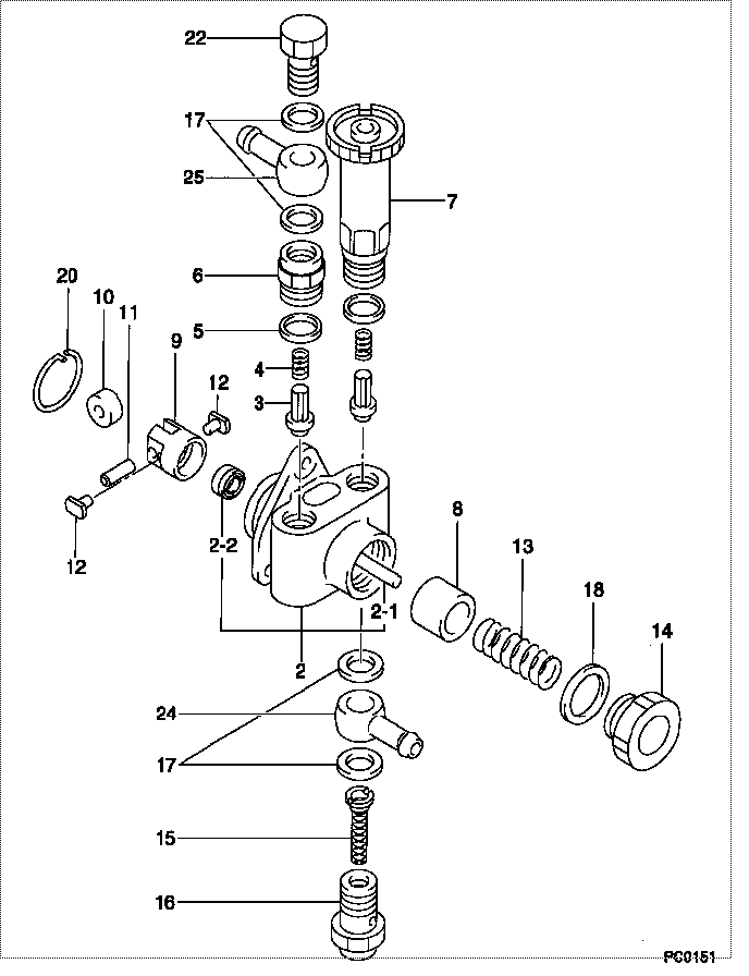
| 000. | [01] | 09210-01231 | PUMP ASSY, FUEL FE | |
| 002. | [01] | 09212-00161 | HOUSING SUB-ASSY, | 09212-00161 |
| 002-001. | [01] | 09216-80150 | ROD, FEED PUMP PUS | 09216-80150 |
| 002-001. | [1C] | 09216-80070 | ROD, FEED PUMP PUS | 09216-80070 |
| 002-001. | [1C] | 09216-80060 | ROD, FEED PUMP PUS | 09216-80060 |
| 002-001. | [1C] | 09216-80050 | ROD, FEED PUMP PUS | 09216-80050 |
| 002-001. | [1C] | 09216-80040 | ROD, FEED PUMP PUS | 09216-80040 |
| 002-001. | [1C] | 09216-80030 | ROD, FEED PUMP PUS | 09216-80030 |
| 002-001. | [1C] | 09216-80010 | ROD, FEED PUMP PUS | 09216-80010 |
| 002-001. | [01] | 09216-80150 | ROD, FEED PUMP PUS | 09216-80150 |
| 002-002. | [01] | 94915-02700 | SEAL, OIL | |
| 002-002. | [01] | 94915-00970 | SEAL, OIL | 94915-00970 |
| 003. | [02] | 09212-10011 | VALVE, FEED PUMP C | 09212-10010 |
| 004. | [02] | 09212-40010 | SPRING, FEED PUMP | 09212-40010 |
| 005. | [02] | 09212-50010 | GASKET, CHECK VALV | 09212-50010 |
| 006. | [01] | 09212-70010 | SUPPORT, VALVE | 09212-70010 |
| 007. | [01] | 09213-00220 | PUMP SUB-ASSY, PRI | |
| 008. | [01] | 09217-10011 | PISTON, FEED PUMP | 09217-10010 |
| 009. | [01] | 09217-40030 | TAPPET, FEED PUMP | 09217-40030 |
| 010. | [01] | 09217-60010 | ROLLER, FEED PUMP | 09217-60010 |
| 011. | [01] | 09217-80010 | PIN, FEED PUMP TAP | 09217-80010 |
| 012. | [02] | 09217-90050 | BLOCK, FEED PUMP T | 09217-90050 |
| 013. | [01] | 09218-20040 | SPRING, FEED PUMP | 09218-20040 |
| 014. | [01] | 09218-40021 | PLUG, FEED PUMP PI | 09218-40020 |
| 015. | [01] | 09222-00040 | FILTER, FEED PUMP | 09222-00040 |
| 016. | [01] | 09222-30070 | SCREW, FUEL PIPE H | 09222-30070 |
| 017. | [04] | 09022-20070 | WASHER, FUEL PIPE | 09022-20070 |
| 018. | [01] | 94901-81240 | WASHER, COPPER PLA | 94901-81240 |
| 020. | [01] | 94907-20940 | RING, SNAP | 94907-20940 |
| 022. | [01] | 94918-00310 | SCREW, HOLLOW | 94918-00310 |
| 024. | [01] | 94918-10420 | NIPPLE, SWIVELING | 94918-10420 |
| 025. | [01] | 94918-10160 | NIPPLE, SWIVELING | 94918-10160 |
Include in #3:
09210-01231
as PUMP ASSY, FUEL FE
Cross reference number
| Part num | Firm num | Firm | Name |
| 09210-01231 | PUMP ASSY, FUEL FE |
Information:
The engine is cooled by forced circulation of coolant by the water pump.(1) Water Pump The water pump is driven by V-belt from the centrifugal pump installed on the front of the crankcase. A backward type impeller is press fitted at the rear shaft end of the water pump.A unit seal is installed between the impeller and water pump that prevents leakage of coolant. There is a drain hole provided at the bottom of the water pump case, which ensures that coolant, should it leak from the unit seal, does not enter bearings.One of the ball bearings is sealed and they are lubricated by grease packed in the water pump case. Grease can be supplied through the grease nipple.(2) Thermostat The thermostat is bottom bypass type.The thermostat pellet, of wax pellet type, contains a special wax which changes from a solid to liquid state and vice versa, depending on heat, and consequent change in its volume causes the valve to open or close, thereby changing the quantity of coolant which flows into the radiator and water pump (bypass side) to control the coolant temperature. A jiggle valve is provided in the air purge hole of the thermostat to quickly increase the coolant temperature.The jiggle valve is in down position by its own weight when the engine is stationary. When pouring in coolant, the air in the system is flown into the radiator through the clearance between the air purge hole and jiggle valve.When the engine is started, coolant circulates and the jiggle valve is forced upward by the hydraulic pressure. As a result, the valve closes the air purge hole, preventing outflow of coolant through the air purge hole.(3) Radiator The radiator, with a tube-and-corrugated-fin type core (and with a reserve tank on some models), not only cools the engine coolant but also separates vapor from liquid water and regulates pressure in the cooling system. The pressure cap regulates the pressure in the cooling system. When the pressure builds up in the system that exceeds a predetermined level, the pressure valve compresses the pressure spring, releasing the excessive pressure through the overflow pipe into the atmosphere.If equipped with a reserve tank, the coolant that has overflowed is channeled into it.When the coolant temperature drops and negative pressure builds up in the system, the vent valve opens to take in air to prevent the radiator from becoming deformed.If equipped with a reserve tank, coolant is taken from the reserve tank to prevent the radiator from becoming deformed and to keep the quantity of coolant in the system constant.If equipped with a pressure release lever on the cap, raising the lever upright opens the pressure valve and releases the pressure in the cooling system.2. Specifications
3. Service Standards
3.1 Service Standards Table
3.2 Tightening Torque Table
4. Special Tool
5. Service Procedure
5.1 Cooling Fan
Removal and installation
5.2 Water Pump
Removal and installation
Disassembly and inspection
Disassembly and Inspection Procedure (1) Remove the flange using the special tool, Gear Puller. (2) Remove the impeller using the special tool, Water Pump