Information pump assy, fuel fe
Rating:
Scheme ###:
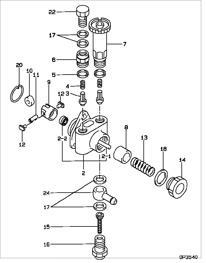
| 000. | [01] | 09210-00743 | PUMP ASSY, FUEL FE | |
| 002. | [01] | 09212-00161 | HOUSING SUB-ASSY, | 09212-00161 |
| 002-001. | [01] | 09216-80150 | ROD, FEED PUMP PUS | 09216-80150 |
| 002-001. | [1C] | 09216-80070 | ROD, FEED PUMP PUS | 09216-80070 |
| 002-001. | [1C] | 09216-80060 | ROD, FEED PUMP PUS | 09216-80060 |
| 002-001. | [1C] | 09216-80050 | ROD, FEED PUMP PUS | 09216-80050 |
| 002-001. | [1C] | 09216-80040 | ROD, FEED PUMP PUS | 09216-80040 |
| 002-001. | [1C] | 09216-80030 | ROD, FEED PUMP PUS | 09216-80030 |
| 002-001. | [1C] | 09216-80010 | ROD, FEED PUMP PUS | 09216-80010 |
| 002-002. | [01] | 94915-00970 | SEAL, OIL | 94915-00970 |
| 002-002. | [01] | 94915-02700 | SEAL, OIL | |
| 003. | [02] | 09212-10011 | VALVE, FEED PUMP C | 09212-10010 |
| 004. | [02] | 09212-40010 | SPRING, FEED PUMP | 09212-40010 |
| 005. | [02] | 09212-50010 | GASKET, CHECK VALV | 09212-50010 |
| 006. | [01] | 09212-70010 | SUPPORT, VALVE | 09212-70010 |
| 007. | [01] | 09213-00220 | PUMP SUB-ASSY, PRI | |
| 008. | [01] | 09217-10011 | PISTON, FEED PUMP | 09217-10010 |
| 009. | [01] | 09217-40030 | TAPPET, FEED PUMP | 09217-40030 |
| 010. | [01] | 09217-60010 | ROLLER, FEED PUMP | 09217-60010 |
| 011. | [01] | 09217-80010 | PIN, FEED PUMP TAP | 09217-80010 |
| 012. | [02] | 09217-90050 | BLOCK, FEED PUMP T | 09217-90050 |
| 013. | [01] | 09218-20040 | SPRING, FEED PUMP | 09218-20040 |
| 014. | [01] | 09218-40021 | PLUG, FEED PUMP PI | 09218-40020 |
| 015. | [01] | 09222-00040 | FILTER, FEED PUMP | 09222-00040 |
| 016. | [01] | 09222-30070 | SCREW, FUEL PIPE H | 09222-30070 |
| 017. | [04] | 09022-20070 | WASHER, FUEL PIPE | 09022-20070 |
| 018. | [01] | 94901-81240 | WASHER, COPPER PLA | 94901-81240 |
| 020. | [01] | 94907-20940 | RING, SNAP | 94907-20940 |
| 022. | [01] | 94918-00310 | SCREW, HOLLOW | 94918-00310 |
| 024. | [01] | 94918-10160 | NIPPLE, SWIVELING | 94918-10160 |
Include in #3:
09000-06680
as PUMP ASSY, FUEL FE
09210-00743
Cross reference number
| Part num | Firm num | Firm | Name |
| 09210-00743 | PUMP ASSY, FUEL FE |
Information:
Change Coolant Element
At operating temperature, the engine coolant is hot and under pressure.Steam can cause personal injury.Check the coolant level only when the engine is stopped and the radiator fill cap is cool enough to touch with your bare hand.Remove the fill cap slowly to relieve pressure.Cooling system conditioner contains alkali. Avoid contact with skin and eyes to prevent personal injury.
All water is corrosive at engine operating temperatures. Use a Caterpillar coolant conditioner element to treat either plain water or ethylene glycol solution.Do not use Caterpillar coolant conditioner elements with Dowtherm 209 Full-Fill coolant. Follow recommendations provided with Dowtherm 209 Full-Fill coolant.
Use a Caterpillar precharge element when the cooling system is drained and refilled. This will establish the proper initial conditioner concentration.Use a Caterpillar maintenance element every 250 service hours thereafter, to maintain the proper conditioner concentration.Contact your Caterpillar dealer for the correct element for your cooling system.If the coolant conditioner elements have been regularly changed every 250 service hours, the change period for engine coolant can be extended to 4000 hours.Refer to the Maintenance (Lubrication and Maintenance) Guide for the procedures to change the antifreeze solution or flush the cooling system. 1. Remove the radiator cap slowly to relieve pressure in the cooling system. 2. Close the inlet valve and the outlet valve at the element base. Turn each handle clockwise to close each valve. 3. Remove the coolant conditioner element. Discard the element. 4. Clean the element mounting base. Make certain all of the old element gasket material is removed.5. Use the correct precharge or maintenance element for your cooling system. Elements are sized according to the cooling system capacity. 6. Coat the seal of the element with a thin film of clean engine oil or antifreeze. 7. Install the element. Tighten it until the seal contacts the base, then tighten it an additional 3/4 turn. 8. Open the inlet valve and the outlet valve. 9. Maintain the coolant level above the low level plate. 10. Clean and install the radiator cap.11. Start the engine and check for leaks.Brakes
Inspect - Adjust
The machine must be level, the bowl lowered, and the parking brake applied.1. Block the wheels securely.2. Start the engine. 3. When the air pressure reaches the NORMAL range, stop the engine. 4. Release the parking/emergency brake. 5. Measure the distance from the rotochamber to the slack adjuster clevis retaining pin. 6. Apply the service brake and measure the amount of travel of the rod. If the travel is 76 mm (3 inches) or more, adjust the brake.7. Measure the brake rotochamber rod travel of all four wheel brakes. Scraper rotochambers are located inside the push frame.To Adjust
1. Loosen the adjustment locking bolt. 2. Turn the adjusting bolt, as required, until the travel is 41 mm (1.62 inches). 3. Tighten the locking bolt. 4. Apply and release the brakes, watching the rotochamber rod for binding.5. Observe the diaphragm for leaks. 6. Start the engine and allow air pressure to reach 690 kPa (100 psi) or in