Information pump assy, injecti
Nozzle:
0935005880
Rating:
KIT List:
| Pump assy, fuel fe | 1922900060 |
| Body assy, injecti | 1904400320 |
| Governor assy, mec | 1908900170 |
Components :
| 001. | PUMP ASSY, INJECTI | 09200-05610 |
| 002. | PUMP ASSY, FUEL FE | 09210-01291 |
| 003. | BODY ASSY, INJECTI | 19010-00901 |
| 004. | GOVERNOR ASSY, MEC | 19080-07100 |
Scheme ###:
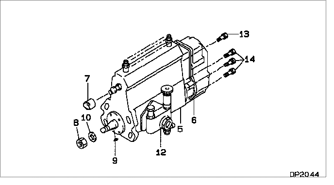
| 000. | [01] | 09200-05610 | PUMP ASSY, INJECTI | 32A6504640 |
| 005. | [01] | 19010-00901 | BODY ASSY, INJECTI | |
| 006. | [01] | 19080-07100 | GOVERNOR ASSY, MEC | |
| 007. | [01] | 09001-80081 | COVER, CONTROL RAC | 09001-80081 |
| 008. | [01] | 94905-03570 | NUT, HEXAGON | |
| 009. | [1C] | 94913-00360 | KEY, WOODRUFF | |
| 009. | [1C] | 94913-00340 | KEY, WOODRUFF | |
| 009. | [1C] | 94913-00320 | KEY, WOODRUFF | |
| 009. | [1C] | 94913-00300 | KEY, WOODRUFF | |
| 010. | [01] | 94901-50590 | WASHER, SPRING | |
| 012. | [01] | 09210-01291 | PUMP ASSY, FUEL FE | 34461-09060 |
| 013. | [01] | 91518-08221 | BOLT, W/WASHER | 91518-08221 |
| 014. | [06] | 91418-06161 | BOLT, W/WASHER | 91418-06161 |
Include in #3:
09200-05610
as PUMP ASSY, INJECTI
Cross reference number
| Part num | Firm num | Firm | Name |
| 09200-05610 | 32A6504640 | PUMP ASSY, INJECTI | |
| 32A6504640 | MITSUBISHI | PUMP ASSY, INJECTI |
Information:
1. Put cylinder head assembly (1) in position on tool group (A). 2. Put compression on valve spring (2) with tool (C). 3. Remove spring locks (3). 4. Remove tool (C). Remove valve spring cap (2) and valve springs (4). 5. Remove washer (5) and O-ring seal (8) from valve (7).6. Remove seal (6). Remove valve (7). 7. Check the valve spring tension with tool (B). The outer spring force must be 180 9 N (40 2 lb.). The length of the spring under test force must be 27.4 mm (1.08 in.). The free length after test must be 45.2 mm (1.78 in.). The inner spring force must be 68.5 9 N (15.4 2 lb.). The length of the spring under test force must be 23.88 mm (.940 in.). The length after test must be 39.6 mm (1.56 in.).8. Do Steps 1 through 8 again for the remainder of the valves. If the cylinder head is equipped with removable valve guides, refer to module SENB8082-06, System Operating Testing And Adjusting Specifications, 4.236 And 4.2482 Diesel Engines For Lift Trucks.Install Valves
1. Put clean engine oil on the valve stems.2. Install valve (3), washer (2) and seal (1).
The closed coil of the spring must be toward the cylinder head.
3. Install springs (5) and valve spring cap (4). 4. Use tool (A), and put springs under compression, and install O-ring seal on the valve. Exhaust valves have an extra O-ring seal on them.
Locks (6) can be thrown from the valve when tool (A) is released if they are not in their correct position on the valve stem.
5. Use tool (B), and install locks (6) that hold the springs in place.6. Remove tool (A), and hit the top of the valve with a plastic hammer to be sure the locks are in their correct position on the valve.7. Do Steps 1 through 6 again for the remainder of the valves.End By:a. install cylinder head assemblyb. install water temperature regulatorc. install fuel filterd. install fuel injection nozzle assembliese. install inlet manifold